Eureka AIR delivers breakthrough ideas for toughest innovation challenges, trusted by R&D personnel around the world.

Organic-inorganic hybrid integrated variable optical attenuator and preparation method thereof

A technology of hybrid integration and variable light, which is applied in light guides, optics, instruments, etc., can solve the problems of limiting device scale and integration, small thermo-optic coefficient, and large power consumption, and achieves easy mass production and high device performance. Low power consumption and compact structure

Pending Publication Date: 2022-02-25
JILIN UNIV
View PDF1 Cites 5 Cited by
  • Summary
  • Abstract
  • Description
  • Claims
  • Application Information

AI Technical Summary

Problems solved by technology

Silica waveguide has low coupling loss and good thermal stability, but its thermo-optic coefficient is small, and the thermo-optic variable optical attenuator (Variable Optical Attenuator, VOA) used to prepare it consumes a lot of power
[0003] At present, most integrated optical devices are based on two-dimensional planar optical waveguide structures. When the integration level of devices gradually increases, two-dimensional integrated optical waveguide devices will introduce a large number of waveguide intersections, thereby introducing crosstalk and loss, limiting device scale and integration. degree of further improvement

Method used


Image

  • Organic-inorganic hybrid integrated variable optical attenuator and preparation method thereof
  • Organic-inorganic hybrid integrated variable optical attenuator and preparation method thereof
  • Organic-inorganic hybrid integrated variable optical attenuator and preparation method thereof

Examples


Embodiment Construction

[0055] The technical solutions in the embodiments of the present invention will be clearly and completely described below in conjunction with the accompanying drawings in the embodiments of the present invention. Obviously, the described embodiments are only part of the embodiments of the present invention, not all embodiments. The embodiments of the present invention and all other embodiments obtained by persons of ordinary skill in the art without making creative efforts all belong to the protection scope of the present invention.

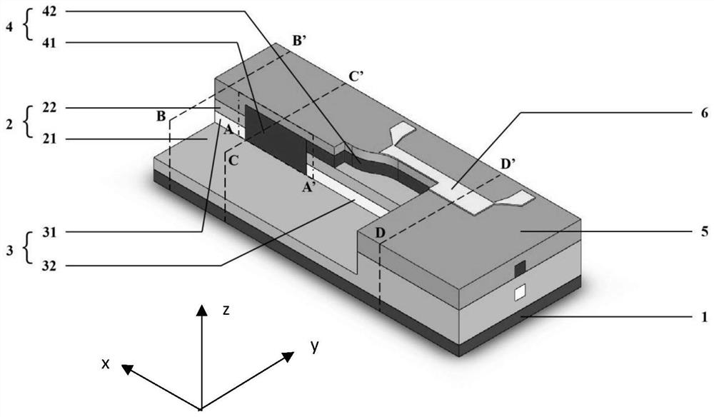
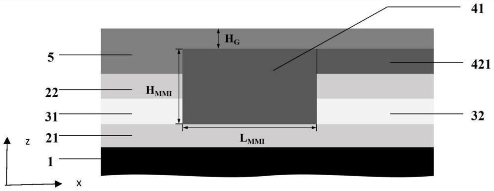
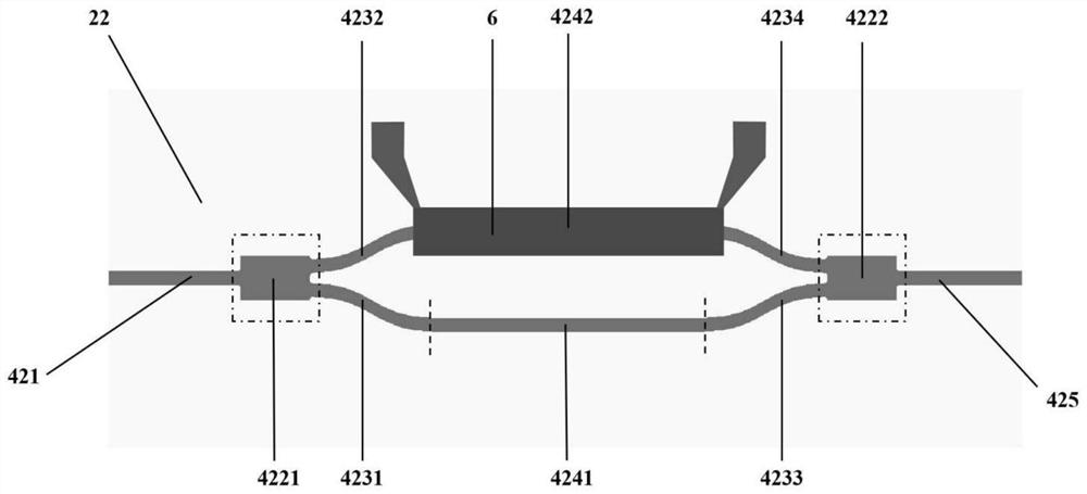
[0056] as attached figure 1 As shown, it is a schematic cross-sectional view of the organic-inorganic hybrid integrated variable optical attenuator of the present invention, exposing the coated silica cladding (2), silica core waveguide (3), polymer core waveguide (4) and other structures. The organic-inorganic hybrid integrated variable optical attenuator consists of the following seven parts from bottom to top:

[0057] 1) silicon substrate ...


PUM

PropertyMeasurementUnit
lengthaaaaaaaaaa
widthaaaaaaaaaa
thicknessaaaaaaaaaa

Abstract

The invention discloses an organic-inorganic hybrid integrated variable optical attenuator and a preparation method thereof, and belongs to the technical field of planar optical waveguide devices and preparation thereof. The organic-inorganic hybrid integrated variable optical attenuator is composed of a silicon substrate, a silicon dioxide lower cladding layer, a germanium-doped silicon dioxide input waveguide and a germanium-doped silicon dioxide output waveguide which are of strip-shaped structures, an interlayer converter based on a vertical MMI structure, a boron and phosphorus-doped silicon dioxide upper cladding layer, a 1 * 1 Mach-Zehnder thermo-optical switch, a polymer upper cladding layer and a heating electrode, wherein the refractive indexes of the input waveguide and the output waveguide are larger than the refractive index of the silicon dioxide upper cladding. The vertical MMI is compact in structure, a VOA device of a traditional inorganic PLC is replaced with a polymer thermo-optical switch type VOA device, and transmission of light from a lower-layer inorganic waveguide to an upper-layer polymer waveguide is achieved; the light transmission power is efficiently adjusted, device power consumption is low, and monolithic integration of organic and inorganic photonic devices is achieved; and the organic-inorganic hybrid integrated variable optical attenuator is compatible with an existing silicon dioxide PLC technology, is easy for large-scale production and low in cost.

Description

technical field [0001] The invention belongs to the technical field of planar optical waveguide devices and their preparation, and in particular relates to an organic-inorganic hybrid integrated variable optical attenuator and a preparation method thereof. Background technique [0002] Variable Optical Attenuator (VOA) is one of the most basic passive devices in optical communication, and has been widely used in Wavelength Division (De) Multiplex (WDM) networks to realize the optical power between channels in the system. Dynamic monitoring of equalization and transmission systems. Silica waveguide has low coupling loss and good thermal stability, but its thermo-optic coefficient is small, so the thermo-optic variable optical attenuator (Variable Optical Attenuator, VOA) used to prepare it consumes a lot of power. Compared with inorganic materials, organic polymer materials have the characteristics of low thermal conductivity and high thermo-optic coefficient, and the prepar...

Claims


Application Information

Patent Timeline
Patent Type & Authority Applications(China)
IPC IPC(8): G02B6/12G02B6/26
CPCG02B6/12002G02B6/266G02B2006/12071G02B2006/12166
Inventor 丁颖智尹悦鑫许馨如姚梦可梁佳琦吕昕雨张大明
Owner JILIN UNIV
Why Eureka
Eureka Blog
Learn More