Supercharge Your Innovation With Domain-Expert AI Agents!

Full-load denitration device and denitration method for circulating fluidized bed boiler

A circulating fluidized bed, full-load technology, applied in chemical instruments and methods, separation methods, gas treatment, etc., can solve problems such as failure to meet ultra-low emission standards and decline in denitrification efficiency, achieve small space occupation, and reduce ozone Energy consumption and the effect of improving denitrification efficiency

Pending Publication Date: 2022-03-04
北京华能长江环保科技研究院有限公司 +1
View PDF0 Cites 0 Cited by
  • Summary
  • Abstract
  • Description
  • Claims
  • Application Information

AI Technical Summary

Problems solved by technology

However, SNCR technology has certain requirements on the reaction zone temperature (800°C~900°C, denitrification efficiency ~75%). During the start-up stage or low-load operation stage, the temperature drop in the reaction zone will greatly reduce the denitrification efficiency, which cannot meet the ultra-low emission standard. (≤50mg / Nm 3 )

Method used


Image

  • Full-load denitration device and denitration method for circulating fluidized bed boiler
  • Full-load denitration device and denitration method for circulating fluidized bed boiler
  • Full-load denitration device and denitration method for circulating fluidized bed boiler

Examples


Embodiment 1

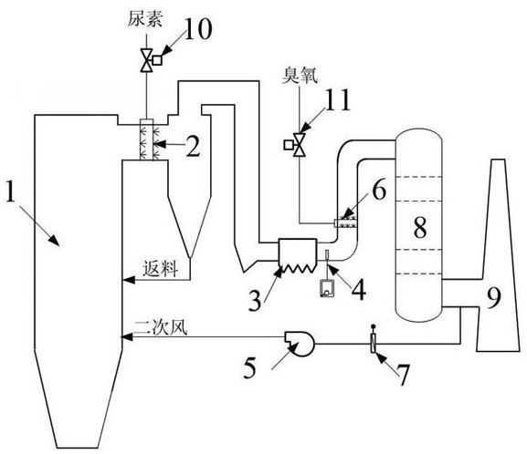
[0032] A circulating fluidized bed boiler full-load denitrification device, which consists of: boiler 1, SNCR spray gun 2, dust collector 3, NOx monitor 4, recirculation fan 5, ozone spray gun 6, desulfurization tower 8 and chimney 9;

[0033] The SNCR spray gun is inserted into the outlet flue of the boiler furnace, and the flue gas of the boiler furnace is discharged through the chimney after passing through the dust collector and the desulfurization tower;

[0034] The baffle valve is arranged in the flue leading out between the desulfurization tower and the chimney, and the recirculation fan is arranged after the baffle valve.

[0035] The ozone spray gun is arranged in the flue between the NOx monitor and the desulfurization tower;

[0036] A recirculation pipeline is drawn between the desulfurization tower and the chimney, a baffle valve 7 is arranged on the recirculation pipeline, and a recirculation fan 5 is arranged behind the baffle valve;

[0037] The SNCR spray gu...

Embodiment 2

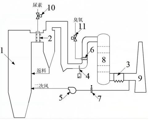
[0040] According to the circulating fluidized bed boiler full-load denitrification device described in embodiment 1, the desulfurization tower is a scrubber, the dust collector is arranged at the front flue of the scrubber, and the NOx monitor It is fixed at the rear flue of the dust collector.

Embodiment 3

[0042] According to the circulating fluidized bed boiler full-load denitrification device described in Example 1, the desulfurization tower is a semi-dry desulfurization tower, and the semi-dry desulfurization tower adopts a conventional bubble tower, and the dust collector is arranged in the The rear flue of the semi-dry desulfurization tower.


PUM


Abstract

The invention discloses a full-load denitration device and method for a circulating fluidized bed boiler. A selective non-catalytic reduction method is generally adopted for denitration of the circulating fluidized bed boiler, the method does not need a catalyst, urea or ammonia is commonly used, NOx is reduced into N2, and the process is simple. The boiler is low in load, flue gas recirculation is adopted for reducing original emission of NOx, meanwhile, NOx is converted into high-valence oxides which are soluble in water in cooperation with ozone oxidation, the high-valence oxides are washed and removed, and no secondary pollution is generated. The system comprises a boiler (1), an SNCR (selective non-catalytic reduction) spray gun (2), an NOx monitor (4), an ozone spray gun (6), a desulfurizing tower (8), a recirculation fan (5) and a chimney (9), the SNCR spray gun is inserted into a boiler furnace outlet flue, and boiler flue gas passes through the desulfurization tower and then is discharged through a chimney; the recirculating fan is arranged behind the flue baffle valve, and recirculating flue gas is introduced into the boiler hearth; and the ozone spray gun is arranged in a flue between the NOx monitor and the desulfurization tower. The invention is used for the full-load denitration device and the denitration method of the circulating fluidized bed boiler.

Description

technical field [0001] The invention belongs to the field of boiler flue gas pollutant control and environmental protection, and in particular relates to a full-load denitrification device and method for a circulating fluidized bed boiler. Background technique [0002] Nitrogen oxides (NOx) produced by coal combustion in circulating fluidized bed boilers are one of the main air pollutants, causing serious environmental problems. Selective non-catalytic reduction (SNCR) is generally used for denitrification of circulating fluidized bed boilers. This method does not use catalysts, and urea or ammonia is commonly used to reduce NOx to N. 2 , the process is simple. However, SNCR technology has certain requirements on the reaction zone temperature (800°C~900°C, denitrification efficiency ~75%). During the start-up stage or low-load operation stage, the temperature drop in the reaction zone will greatly reduce the denitrification efficiency, which cannot meet the ultra-low emissi...

Claims


Application Information

Patent Timeline
IPC IPC(8): B01D53/56B01D53/75B01D53/79B01D53/76B01D53/30
CPCB01D53/56B01D53/79B01D53/75B01D53/76B01D53/30B01D2251/104B01D2251/2067B01D2258/0283
Inventor 李昱喆钟犁余长开苏林陈飞云屈志强李楠马骁骅茹宇张茂龙韩立鹏
Owner 北京华能长江环保科技研究院有限公司
Features
  • R&D
  • Intellectual Property
  • Life Sciences
  • Materials
  • Tech Scout
  • Unparalleled Data Quality
  • Higher Quality Content
  • 60% Fewer Hallucinations
Learn More