
Eddy micro-mixer based on array type micro heat source and mixing method of eddy micro-mixer

A micro-mixer and array-type technology, applied in the field of optofluidics, can solve problems such as inconvenient capture, fluid mixing limitation, and unstable bubbles, and achieve the effects of short reaction time, avoiding pollution and damage, and simple and easy production methods

Pending Publication Date: 2022-03-11
SOUTH CHINA NORMAL UNIVERSITY
View PDF5 Cites 0 Cited by
  • Summary
  • Abstract
  • Description
  • Claims
  • Application Information

AI Technical Summary

Problems solved by technology

So far, bubble-based acoustic micromixers have been used to characterize enzymatic reactions, enhance DNA hybridization, and develop advanced optofluidic devices. However, the instability and inconvenient trapping of bubbles still have great limitations in promoting fluid mixing.

Method used


Image

  • Eddy micro-mixer based on array type micro heat source and mixing method of eddy micro-mixer
  • Eddy micro-mixer based on array type micro heat source and mixing method of eddy micro-mixer
  • Eddy micro-mixer based on array type micro heat source and mixing method of eddy micro-mixer

Examples


Embodiment 1

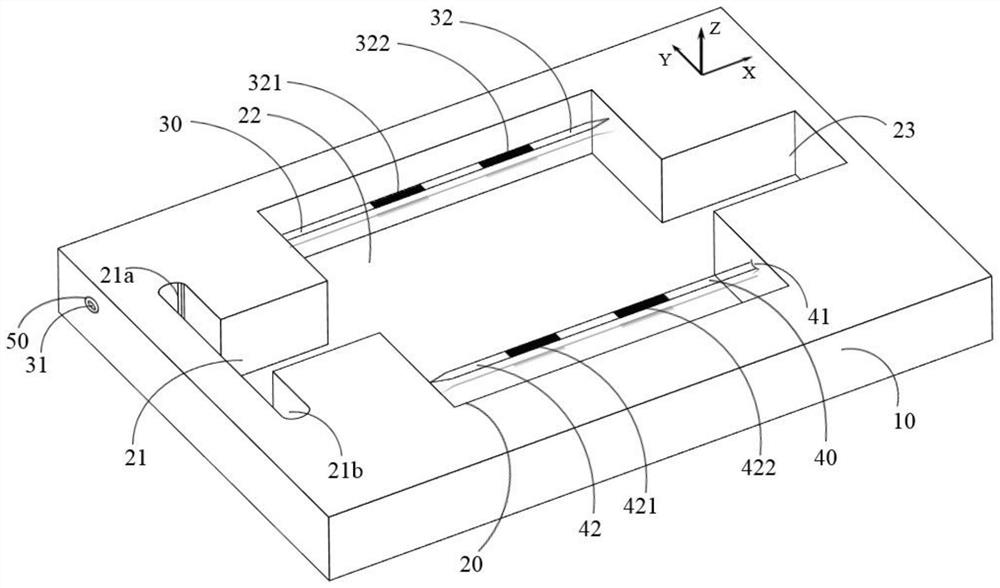
[0049] Such as figure 1 As shown, the vortex micro-mixer based on the arrayed micro heat source according to Embodiment 1 of the present invention includes a substrate 10, a micro flow channel 20, a first array type micro heat source 30 and a second array type micro heat source 40, wherein the micro flow channel 20 Set in the base 10, it includes an input tank 21, a mixing tank 22 and an output tank 23 connected in sequence. The input tank 21 is used to inject at least two different liquids, and the output tank 23 is used to discharge the mixed liquid in the mixing tank 22. The first array type micro heat source 30 and the second array type micro heat source 40 are spaced from each other and can be movably arranged on the substrate 10, each array type micro heat source includes an optical signal input end and an optical signal excitation end, and the optical signal input end is used for When the optical signal of predetermined power is connected, the optical signal excitation ...

Embodiment 2

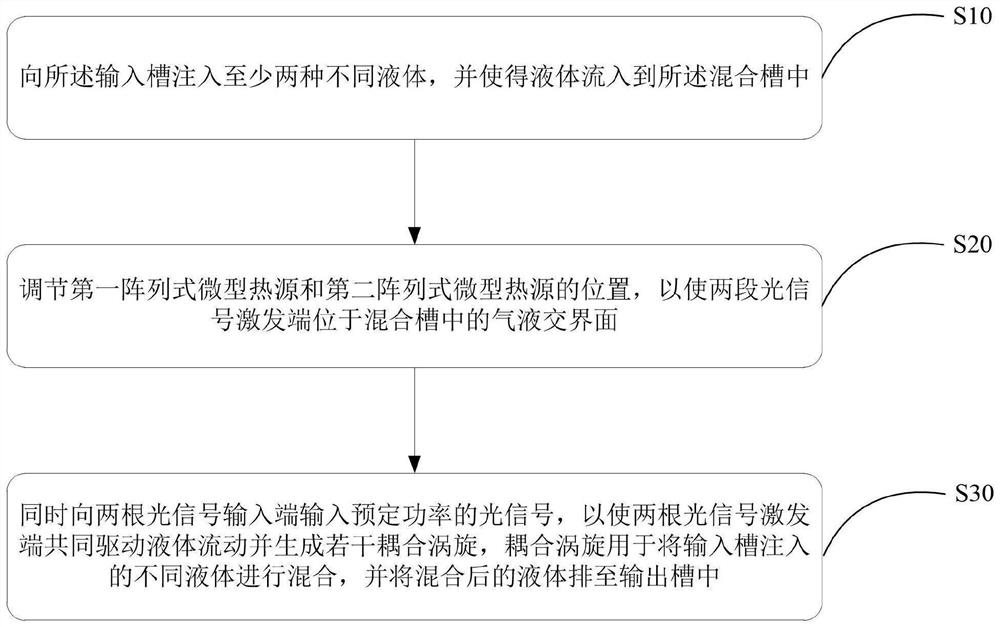
[0059] As shown in the figure, the mixing method of the vortex micro-mixer based on the array micro-heat source provided in the second embodiment includes the following steps:

[0060] Step S10: inject at least two different liquids into the input tank 21, and make the liquids flow into the mixing tank 22;

[0061] Step S20: adjusting the positions of the first array micro heat source 30 and the second array micro heat source 40, so that the excitation ends of the two sections of optical signals are located at the gas-liquid interface in the mixing tank 22;

[0062] Step S30: Simultaneously input optical signals of predetermined power to the two optical signal input terminals, so that the two optical signal excitation terminals jointly drive the liquid flow and generate several coupling vortices, which are used to inject different liquids into the input tank 21 Mixing takes place and the mixed liquid is discharged to output tank 23 .

[0063] Specifically, in step S10 , liqui...


PUM

PropertyMeasurementUnit
distanceaaaaaaaaaa
diameteraaaaaaaaaa
melting pointaaaaaaaaaa

Abstract

The invention discloses a vortex micro mixer based on an array type micro heat source and a mixing method of the vortex micro mixer. The vortex micro-mixer comprises: a substrate; the microfluidic channel is arranged in the substrate and comprises an input groove, a mixing groove and an output groove which are communicated in sequence, the input groove is used for injecting at least two different liquids, and the output groove is used for discharging the mixed liquids in the mixing groove; the first array type micro heat source and the second array type micro heat source are movably arranged on the substrate at intervals, each array type micro heat source comprises an optical signal input end and an optical signal excitation end, the optical signal input end is used for accessing optical signals with preset power, the optical signal excitation end is arranged on a gas-liquid interface in the mixing tank, and the optical signal excitation end is used for receiving optical signals with preset power. The optical signal excitation ends of the first array type micro heat source and the second array type micro heat source are jointly used for generating coupling vortexes in liquid so as to mix at least two different kinds of liquid. The vortex micro-mixer is mild in operation condition, flexible in operation, high in adjustability and high in efficiency.

Description

technical field [0001] The invention belongs to the field of optofluidic technology, and in particular relates to a vortex micro-mixer based on an array micro heat source and a mixing method thereof. Background technique [0002] Due to their short reaction time, high throughput, and low reagent consumption, microfluidic devices can be effectively applied in many fields, including biomedical diagnostics, drug delivery, chemical synthesis, and enzymatic reactions. However, the rate-limiting step in the detection of chemical and biological reagents is usually the process of mixing the sample with the reagent. This phenomenon is due to the low rate of diffusive transport in liquid systems, even at the microscale. To achieve microfluidic applications that require mixing, many micromixing methods have been reported. These methods include: chaotic advection method, hydrodynamic focusing method, electrodynamically driven mixing method, three-dimensional combined mixing method, me...

Claims


Application Information

Patent Timeline
Patent Type & Authority Applications(China)
IPC IPC(8): B01F33/30B01F25/00B01F23/40B01L3/00
CPCB01L3/50273B01L2400/0403
Inventor 邢晓波罗芳婧周瑞雪李瑶吴家隐栾天阳徐宇夏鹏飞郑志东李恒杨观杰
Owner SOUTH CHINA NORMAL UNIVERSITY
Learn More