Radar positioning method and device, storage medium and terminal

A radar positioning and pose estimation technology, applied in the fields of computer vision and machine perception, can solve the problems of limited hardware service life, large limitations, and large storage space requirements, so as to improve the scope of application, reduce the amount of calculation, and computing power The effect of low consumption

Pending Publication Date: 2022-03-22
SHANGHAI TECH UNIV
View PDF0 Cites 0 Cited by
  • Summary
  • Abstract
  • Description
  • Claims
  • Application Information

AI Technical Summary

Problems solved by technology

[0002] For the Absolute Indoor Localization problem (Absolute Indoor Localization), some solutions in the prior art rely on one or more passive wireless communication sensors to assist positioning, and detect the target position by receiving electromagnetic waves radiated or reflected by the target. For example, radio frequency identifiers, Wi-Fi, Bluetooth beacons, ultrasonic beacons, etc., have relatively large limitations and require professionals to enter the site in advance to arrange and debug, which is time-consuming, laborious and expensive, and the service life of the hardware is limited; another part of the solution uses The known map is used to assist positioning. The core algorithm is based on Monte Carlo Localization, Stochastic Gradient Descent or Voronoi Segmentation. However, since the map needs to be discrete in such methods In order to achieve a certain accuracy, a large amount of information needs to be stored, which inevitably has the disadvantage of large storage space requirements, and a large amount of data needs to be processed when performing positioning tasks, which not only consumes computing resources, but also affects the real-time performance of positioning.

Method used


Image

  • Radar positioning method and device, storage medium and terminal
  • Radar positioning method and device, storage medium and terminal
  • Radar positioning method and device, storage medium and terminal

Examples


Embodiment 1

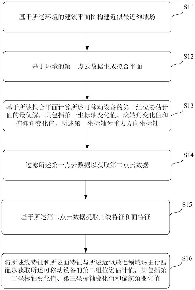
[0027] Such as figure 1 As shown, this embodiment proposes a schematic flow diagram of a radar positioning method, which is applied to a mobile robot, including steps S11 to S16, specifically expressed as follows:

[0028] Step S11. Construct an approximate nearest field field based on the building plan of the environment.

[0029]In a preferred implementation manner of this embodiment, the method of constructing the approximate nearest domain field includes: extracting the geometric elements in the building plan, and constructing a mathematical model, weighting value (greater than 0 and less than 1) and Numbering; dividing the building plan into multiple identical square areas; calculating the distance from the geometric elements in each of the square areas to the center of the area to obtain the preset number of nearest geometric elements in each area; dividing the nearest geometric elements The numbers stored in the corresponding area; Repeatedly divide each square area in...

Embodiment 2

[0065] Such as Figure 5 As shown, the embodiment of the present invention proposes a schematic structural diagram of a radar positioning device, which includes: an approximate nearest field construction module 51, which is used to construct an approximate nearest field based on the building plan of the environment; a radar module 52, which is used to collect The first point cloud data of the environment; the plane fitting module 53 is used to generate a fitting plane based on the first point cloud data of the environment; the first group of pose estimation module 54 is used to calculate the movement based on the fitting plane The optimal solution of the first group of pose estimation values ​​of the robot, which includes the first coordinate axis change value, the roll angle change value and the pitch angle change value, and the first coordinate axis is the gravity direction coordinate axis; the filtering module 55 uses For filtering the first point cloud data to obtain the s...

Embodiment 3

[0069] An embodiment of the present invention provides a computer-readable storage medium, on which a computer program is stored, and when the computer program is executed by a processor, the radar positioning method is implemented.

[0070]Those of ordinary skill in the art can understand that all or part of the steps for implementing the above method embodiments can be completed by hardware related to computer programs. The aforementioned computer program can be stored in a computer-readable storage medium. When the program is executed, it executes the steps of the above-mentioned method embodiments; and the aforementioned storage medium includes: ROM, RAM, magnetic disk or optical disk and other various media that can store program codes.


PUM


Abstract

The invention provides a radar positioning method and device, a storage medium and a terminal, and the method is applied to a mobile device, and comprises the steps: constructing an approximate nearest domain field based on an architectural plan of an environment; generating a fitting plane based on the first point cloud data of the environment; calculating an optimal solution of a first group of pose estimation values of the mobile device based on the fitting plane, wherein the optimal solution comprises a first coordinate axis change value, a roll angle change value and a pitch angle change value; filtering the first point cloud data to obtain second point cloud data; extracting line features and surface features of the second point cloud data based on the second point cloud data; and matching the line features and the surface features with the approximate nearest domain field to obtain a second group of pose estimation values of the mobile equipment, wherein the second group of pose estimation values comprises a second coordinate axis change value, a third coordinate axis change value and a yaw angle change value. According to the invention, the calculation amount and the power consumption can be obviously reduced under the condition of ensuring the positioning precision; the system can be widely applied to the fields of scientific research, entertainment service, building construction, logistics management and the like.

Description

technical field [0001] The invention relates to the fields of computer vision and machine perception, in particular to a radar positioning method, device, storage medium and terminal. Background technique [0002] For the Absolute Indoor Localization problem (Absolute Indoor Localization), some solutions in the prior art rely on one or more passive wireless communication sensors to assist positioning, and detect the target position by receiving electromagnetic waves radiated or reflected by the target. For example, radio frequency identifiers, Wi-Fi, Bluetooth beacons, ultrasonic beacons, etc., have relatively large limitations and require professionals to enter the site in advance to arrange and debug, which is time-consuming, laborious and expensive, and the service life of the hardware is limited; another part of the solution uses The known map is used to assist positioning. The core algorithm is based on Monte Carlo Localization, Stochastic Gradient Descent or Voronoi Se...

Claims


Application Information

Patent Timeline
Patent Type & Authority Applications(China)
IPC IPC(8): G06T7/73G06T7/77G06T7/33G06T7/35G01S7/41G01S13/06
CPCG06T7/74G06T7/77G06T7/337G06T7/35G01S7/41G01S13/06G06T2207/10028G06T2207/10016
Inventor 高翎康智文
Owner SHANGHAI TECH UNIV
Why Eureka
Try Eureka