Waste heat recycling device with flue gas purification mechanism

A waste heat recovery and flue gas purification technology, applied in the direction of clean heat transfer devices, indirect heat exchangers, heat exchanger types, etc., can solve the problems of heat exchange efficiency reduction, pollution, environmental pollution, etc., and achieve loss reduction and use The effect of increasing lifespan

Inactive Publication Date: 2022-03-25
WUXI XIANGLONG GLOBAL TECH CO LTD
View PDF3 Cites 0 Cited by
  • Summary
  • Abstract
  • Description
  • Claims
  • Application Information

AI Technical Summary

Problems solved by technology

[0003] In the prior art, in order to ensure the improvement of the waste heat recovery rate, the waste heat is mostly recovered and utilized at the position where the flue gas is directly discharged. Due to the influence of smoke and dust attached to the outside of the pipe wall, the heat exchange efficiency and waste heat recovery efficiency are reduced, and one side of the waste heat recovery pipe is in direct contact with the flue gas at a higher temperature for a long time, which affects the service life of the waste heat recovery pipe; When removing the dust in the flue gas, bag dust removal and electrostatic dust removal are often used. The equipment required for bag dust removal and electrostatic dust removal takes up a lot of space, and the dust removed by the bag dust removal is in a fluffy state, which makes the fluffy dust contain More nitrogen and sulfur oxides, nitrogen and sulfur oxides are directly discharged into the external environment with the smoke, which is easy to pollute the environment; flue gas purification mostly uses catalytic reduction of nitrogen oxides in the flue gas under the action of a catalyst In this reaction process, in order to ensure that the nitrogen oxides in the flue gas are fully catalytically reduced, the reaction time is long, which limits the transmission of flue gas inside the exhaust pipe, and when the catalyst is deactivated, It is difficult for the staff to find out in time, so that the smoke discharged from the external environment will pollute the environment

Method used


Image

  • Waste heat recycling device with flue gas purification mechanism
  • Waste heat recycling device with flue gas purification mechanism
  • Waste heat recycling device with flue gas purification mechanism

Examples


Embodiment 1

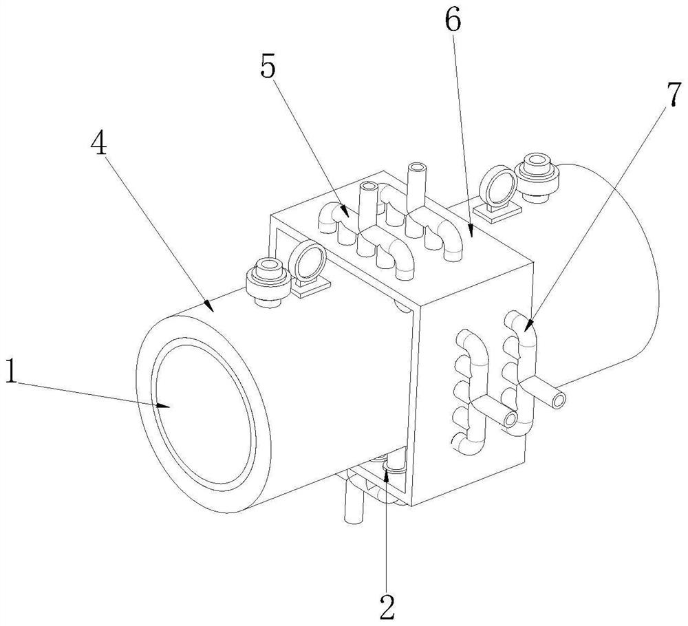
[0041] see Figure 1-7 As shown, the waste heat recovery and utilization device with a flue gas purification mechanism includes a smoke exhaust pipe 1, a longitudinal recovery pipe 5, an outer frame 6 and a horizontal recovery pipe 7, and the upper and lower sides of the outer surface of the smoke exhaust pipe 1 are connected with longitudinal recovery pipes 5 , the left and right sides of the outer surface of the smoke exhaust pipe 1 are connected with horizontal recovery pipes 7, and the outer wall of the smoke exhaust pipe 1 is provided with an outer frame 6 at the position corresponding to the longitudinal recovery pipe 5 and the horizontal recovery pipe 7;

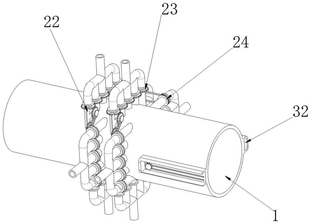
[0042] A waste heat recovery mechanism 2 is provided inside the outer frame 6 corresponding to the position of the exhaust pipe 1. The waste heat recovery mechanism 2 includes a rotating tube 216, and the two ends of the rotating tube 216 are rotatably connected with a rotating sleeve 21. Both ends of the rotating tube...

Embodiment 2

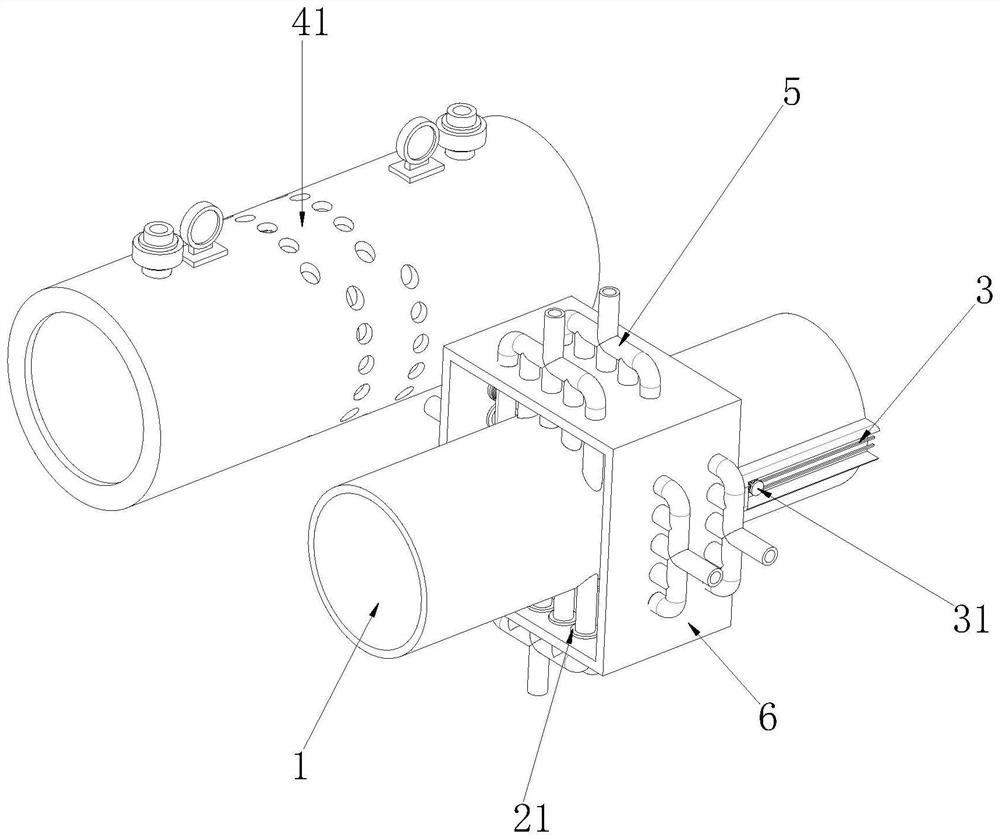
[0046] see figure 2 , Figure 4 and Figure 7-11As shown, the ash removal mechanism 3 is arranged on the outer side wall of the exhaust pipe 1 close to the outer frame 6. The ash removal mechanism 3 includes a transmission chamber 32, and the inner side wall of the transmission chamber 32 is connected to the position corresponding to the third runner 215 through a rotating shaft. There is a fourth runner 34, and the fourth runner 34 is connected to the third runner 215 through a transmission belt 25. The fourth runner 34 is connected to a fourth gear 35 on one side of the outer wall, and the inner wall of the transmission chamber 32 is close to the fourth gear 35. The position is connected with the fifth gear 33 through the rotation of the rotating shaft, the fourth gear 35 and the fifth gear 33 are perpendicular to each other and interfitted with each other, and are driven to rotate, and the fifth gear 33 is connected to the fifth runner 31 on one side of the outer wall. T...

Embodiment 3

[0050] see Figure 8 and Figure 12 As shown, the end of the smoke exhaust pipe 1 away from the outer frame 6 is provided with an auxiliary mechanism 4, the auxiliary mechanism 4 includes a catalytic bed 44, and the outer wall of the connecting pipe on the side of the catalytic bed 44 close to the smoke exhaust pipe 1 is connected with a communication valve 42. An exhaust gas quality detector 45 is connected to the outer wall of the connecting pipe on the side of the bed 44 away from the smoke exhaust pipe 1, and an air collecting hopper 46 is connected to one end of the connecting pipe on the side of the catalytic bed 44 away from the smoke exhaust pipe 1, and the gas collecting hopper 46 is far away from the One side of the catalytic bed 44 is connected to a desulfurization box 47 through a connecting pipe. The interior of the desulfurization box 47 reacts with the sulfur oxides in the flue gas through the lime milk solution to remove the sulfur oxides. The outer wall of the...


PUM


Abstract

The invention relates to a waste heat recovery technology which is used for solving the problems that in the flue gas transmission process, heat loss is much, the service life of heat exchange equipment is shortened due to the influence of high temperature, more substances harmful to the environment exist in discharged smoke dust, the smoke discharging speed in a smoke discharging pipe is limited, and a catalyst is inactivated, so that harmful substances are discharged to pollute the environment. The waste heat recycling device comprises a smoke exhaust pipe, a longitudinal recycling pipe, an outer frame and a transverse recycling pipe. According to the invention, through rotation of the rotating pipe connected with the longitudinal recovery pipe and the transverse recovery pipe, each area of the outer wall of the rotating pipe can be in direct contact with discharged high-temperature flue gas, the service life is prolonged, and removed flue dust is compacted under the action of an extrusion sleeve and then discharged, so that the dust removal efficiency is improved. Nitrogen and sulfur oxides harmful to the environment in discharged smoke dust are reduced, denitration operation is carried out in sequence through the multiple catalytic beds, and the situation that the environment is polluted due to the fact that smoke discharging is blocked and a catalyst is inactivated in the smoke discharging pipe is avoided.

Description

technical field [0001] The invention relates to waste heat recovery technology, in particular to a waste heat recovery and utilization device with a flue gas purification mechanism. Background technique [0002] Waste heat refers to the limitations of history, technology, concept and other factors. Among the energy-consuming devices of industrial enterprises that have been put into operation, the original design has not been rationally utilized. The comprehensive utilization of waste heat is based on the quality of waste heat, according to The sequence of high and low temperature is used step by step, and the high-quality ones can be used in production processes or waste heat power generation. [0003] In the prior art, in order to ensure the improvement of the waste heat recovery rate, the waste heat is mostly recovered and utilized at the position where the flue gas is directly discharged. Due to the influence of smoke and dust attached to the outside of the pipe wall, th...

Claims


Application Information

Patent Timeline
IPC IPC(8): F28D11/04F28F9/013F28F19/01F28G1/08B01D53/86B01D53/56
CPCF28D11/04F28F9/013F28F19/01F28G1/08B01D53/8631B01D53/869
Inventor 邓伟李凯陶梦姣隋春艳
Owner WUXI XIANGLONG GLOBAL TECH CO LTD
Why Eureka
Try Eureka