
Sapphire crystal bar processing system and method

A processing system and sapphire technology, applied in stone processing equipment, metal processing equipment, fine working devices, etc., can solve the problems of low efficiency when sapphire wafer is slotted, and achieve the effect of solving low efficiency and accurate cutting

Pending Publication Date: 2022-04-01
JIANGXI ZHAO CHI SEMICON CO LTD
View PDF10 Cites 0 Cited by
  • Summary
  • Abstract
  • Description
  • Claims
  • Application Information

AI Technical Summary

Problems solved by technology

[0005] In view of this, the purpose of the present invention is to provide a processing system for sapphire crystal rods, which aims to solve the problem of low efficiency in the prior art when grooving sapphire wafers

Method used


Image

  • Sapphire crystal bar processing system and method
  • Sapphire crystal bar processing system and method
  • Sapphire crystal bar processing system and method

Examples


Embodiment 1

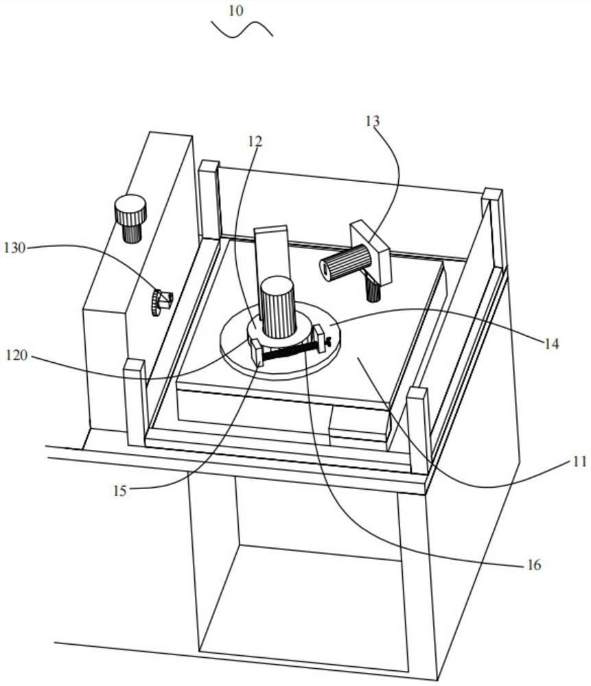
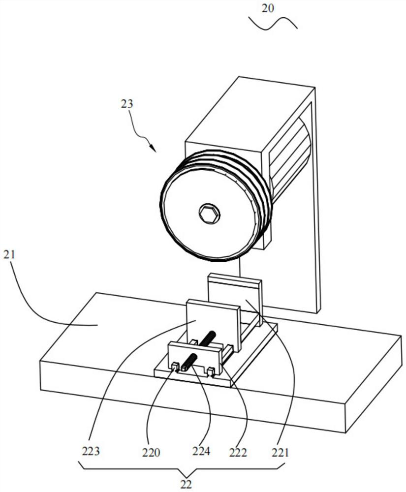
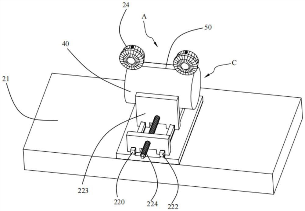
[0041] see Figure 1 to Figure 5 , shows the processing system of the sapphire crystal rod 40 in the first embodiment of the present invention, the processing system of the sapphire crystal rod 40 includes a marking mechanism 10 for cutting marks 50, a slotting mechanism 20 for slotting, and The chamfering mechanism 30 for chamfering, wherein:

[0042] The marking mechanism 10 includes a base 11, a rotating platform 12 disposed on the base 11, and an X-ray generator 13 disposed on the base 11. The rotating platform 12 is used to carry the sapphire crystal rod 40, and the rotating platform 12 is provided with a stopper. The leaning plate is used to lean against the sapphire crystal rod 40 .

[0043] During specific implementation, the sapphire crystal rod 40 is placed upright on the rotating platform 12, and a circular claw plate (not shown) is provided on the rotating platform 12 for fixing the sapphire crystal rod 40, and adjusting the position of the rotating platform 12 to...

Embodiment 2

[0060] see Figure 6 , shows the method for processing a sapphire crystal rod proposed in the second embodiment of the present invention, using the processing system for a sapphire crystal rod in the first embodiment above, and the method includes steps S10-S13.

[0061] Step S10, obtaining the A-direction of the sapphire crystal rod through the marking mechanism, and marking the A-direction of the sapphire crystal rod to obtain a cutting mark.

[0062] Step S11 , clamping the sapphire crystal ingot on the workbench by the clamping assembly, and cutting the sapphire crystal ingot along the cutting mark by using the processing abrasive.

[0063] Step S12, slicing the grooved sapphire ingot.

[0064] Step S13 , placing the slotted and sliced ​​sapphire crystal rod on the suction cup holder, so as to chamfer the grooved and sliced ​​sapphire crystal rod by the chamfering grinder.

[0065] In some optional embodiments of the present invention, after the wafer thickness is automa...


PUM


Abstract

The invention discloses a sapphire crystal bar processing system, comprising: a marking mechanism for cutting and marking a sapphire crystal bar; the grooving mechanism comprises a workbench arranged on the surface grinding machine and a clamping assembly arranged on the workbench, the clamping assembly is used for clamping the sapphire crystal bar, the surface grinding machine is further provided with a machining grinding tool, the machining grinding tool is arranged right opposite to the clamping assembly, and the machining grinding tool is used for machining the sapphire crystal bar. The sapphire crystal bar is slotted along the cutting mark through the machining grinding tool; the chamfering mechanism comprises a suction cup base and a driving mechanism arranged below the suction cup base and used for driving the suction cup base to rotate, the suction cup base is used for bearing the sapphire crystal bar subjected to slotting and slicing, and the chamfering mechanism further comprises a chamfering grinding tool arranged on the side edge of the suction cup base so as to chamfer the sapphire crystal bar subjected to slotting and slicing. According to the sapphire crystal bar machining system, the problem that in the prior art, the efficiency is low when a sapphire wafer is slotted is solved.

Description

technical field [0001] The invention relates to the technical field of sapphire processing, in particular to a processing system and method for a sapphire crystal rod. Background technique [0002] Sapphire is an important material for processing blue light diodes and plays a pivotal role in the semiconductor field. After the sapphire crystal rod is cut into wafers, the edges of the peripheral part will form sharp corners or be slightly broken, which makes the substrate easy to cause substrate cracking and chipping during subsequent processing. Part of the edge is chamfered into rounded corners. On the one hand, wafer chamfering can reduce the adverse effects caused by edge defects, and on the other hand, it will also reduce the wafer stress in the subsequent wafer processing process. The reduction of stress will greatly reduce the damage caused by wafer epitaxy. Slip line defects improve the yield of epitaxy. [0003] At present, 4-inch sapphire substrate wafers are gradu...

Claims


Application Information

Patent Timeline
Patent Type & Authority Applications(China)
IPC IPC(8): B24B27/06B24B9/06B24B41/06B24B47/20B24B49/00B24B55/02B28D5/00B28D7/04
Inventor 赵元亚吴琼琼崔思远
Owner JIANGXI ZHAO CHI SEMICON CO LTD
Learn More