Method for improving laser bending forming precision of single curved surface of fiber metal laminate

A fiber metal laminate and bending forming technology, applied in metal processing, metal processing equipment, manufacturing tools, etc., can solve the problems of non-plastic deformation of metal, affecting the use risk of complex curved surface forming accuracy, and reduce the cumulative rebound deformation. , Improve the accuracy of laser bending forming and suppress interference

Active Publication Date: 2022-04-12
DALIAN UNIV OF TECH
View PDF19 Cites 1 Cited by
  • Summary
  • Abstract
  • Description
  • Claims
  • Application Information

AI Technical Summary

Problems solved by technology

[0005] Aiming at the problem of non-plastic deformation of the underlying metal after laser bending due to the material and structural characteristics of the fiber metal laminate, which further affects the forming acc

Method used


Image

  • Method for improving laser bending forming precision of single curved surface of fiber metal laminate
  • Method for improving laser bending forming precision of single curved surface of fiber metal laminate
  • Method for improving laser bending forming precision of single curved surface of fiber metal laminate

Examples


Embodiment

[0026] Embodiment: Laser scanning forming of glass fiber reinforced aluminum alloy laminates with multiple lines side by side and equidistant single curved surface.

example 1

[0027] Example 1, uncorrected shape sample production (comparative example):

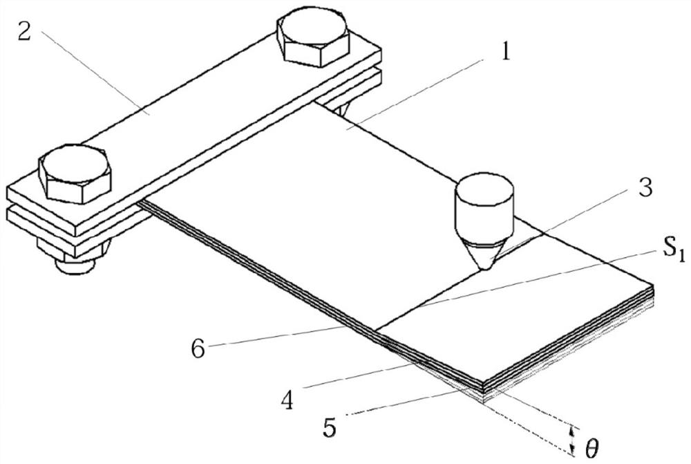
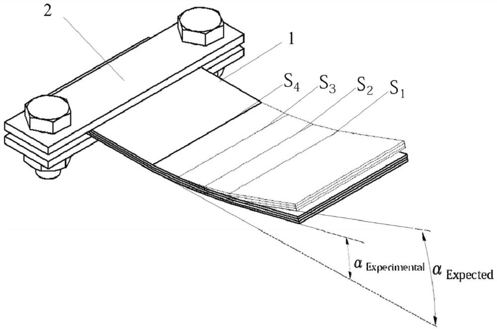
[0028] ①Fiber metal laminate 1 is made of glass fiber reinforced aluminum alloy laminate, the type is GLARE 4B-2 / 3, and the plate is processed into a rectangular sample with a thickness of 1mm, a width of 25mm and a length of 60mm by using an abrasive water jet processing platform . The scanning path is as shown in the figure, the number of scanning tracks N=4, the single-track target bending angle θ=3°, and the scanning distance d=6mm. In order to increase the light absorption rate, scan line S on the upper metal layer 1 , S 2 , S 3 , S4 The position is treated with carbon black. In order to avoid delamination of the plate, the distance between the scanning line and the edge of the plate is L 1 ≥15mm, this embodiment L 1 = 16 mm.

[0029] ② Clamp one end of the fiber metal laminate 1 with a clamp 2 and place it on the workbench of the laser processing machine. Scanning line S along the set u...

example 2

[0031] Example 2, the production of proofreading samples:

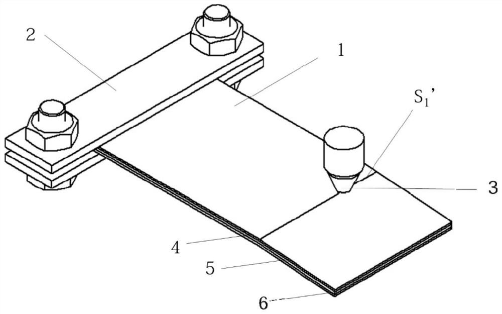
[0032] ① Fiber metal laminate 2 is made of glass fiber reinforced aluminum alloy laminate, the type is GLARE 4B-2 / 3, and the plate is processed into a rectangular sample with a thickness of 1mm, a width of 25mm and a length of 60mm by using an abrasive water jet processing platform . The scanning path on the surface of the upper metal layer is as follows: Figure 4 As shown, the number of scanning tracks N=4, the single-channel bending angle θ=3°, and the scanning pitch P=6mm. The scanning path on the surface of the lower metal layer is as follows: Figure 5 As shown, it is located directly below the scanning path on the surface of the upper metal layer, corresponding to it one by one. In order to increase the light absorption rate, scan line S on the upper metal layer 1 , S 2 , S 3 , S 4 , the lower metal layer scan line S 1 ’, S 2 ’, S 3 ’, S 4 ’ The position is treated with carbon black. To avoid delamin...


PUM

PropertyMeasurementUnit
Thicknessaaaaaaaaaa

Abstract

The invention belongs to the technical field of laser bending forming of fiber metal laminates, and relates to a method for improving laser bending forming precision of a single curved surface of a fiber metal laminate. According to the invention, an upper and lower layer alternate scanning laser bending forming method is adopted, and the elastic recovery deformation of a bending area in laser multi-channel scanning bending forming is corrected. And the upper-layer metal laser bending forming and the lower-layer metal pre-bending laser bending forming based on the temperature gradient mechanism are alternately carried out until the target bending angle is reached. And the lower metal layer and the upper metal layer are plastically deformed, so that the elastic recovery of the formed bending area caused by the interference of subsequent scanning is inhibited. And the single-curved-surface laser bending forming precision of the fiber metal laminate is improved, the internal residual stress of the plate is reduced, and the single-curved-surface technical requirements of the metal laminate are met.

Description

technical field [0001] The invention belongs to the field of laser bending forming of fiber metal laminates, and relates to a method for improving the accuracy of laser bending forming of a single curved surface of fiber metal laminates. The invention can be applied to aircraft fuselages, wings and other single curves with high angular precision In the field of surface skin laser heating and bending forming. Background technique [0002] Compared with the traditional autoclave forming method, laser bending forming can produce compound bending deformation of the plate by controlling the scanning path of the laser beam, which is superior to the autoclave forming method in terms of processing speed, processing flexibility and cost. However, in the single-curved laser bending of fiber metal laminates, when the distance between the two laser scanning paths is small (<15mm), elastic recovery deformation in the bending area will occur, that is, subsequent scanning will affect th...

Claims


Application Information

Patent Timeline
IPC IPC(8): B21D31/00B21C51/00
Inventor 王续跃孙涛尤泉
Owner DALIAN UNIV OF TECH
Why Eureka
Try Eureka