
Reset circuit test system and method for logic built-in self-test
A technology with built-in self-test and reset circuits, applied in static memory, instruments, etc., it can solve the problems of missing coverage of registers and reduce fault coverage, so as to improve fault coverage, save test time, and save resources.
- Summary
- Abstract
- Description
- Claims
- Application Information
AI Technical Summary
Problems solved by technology
Method used
Image


Examples
Embodiment 1
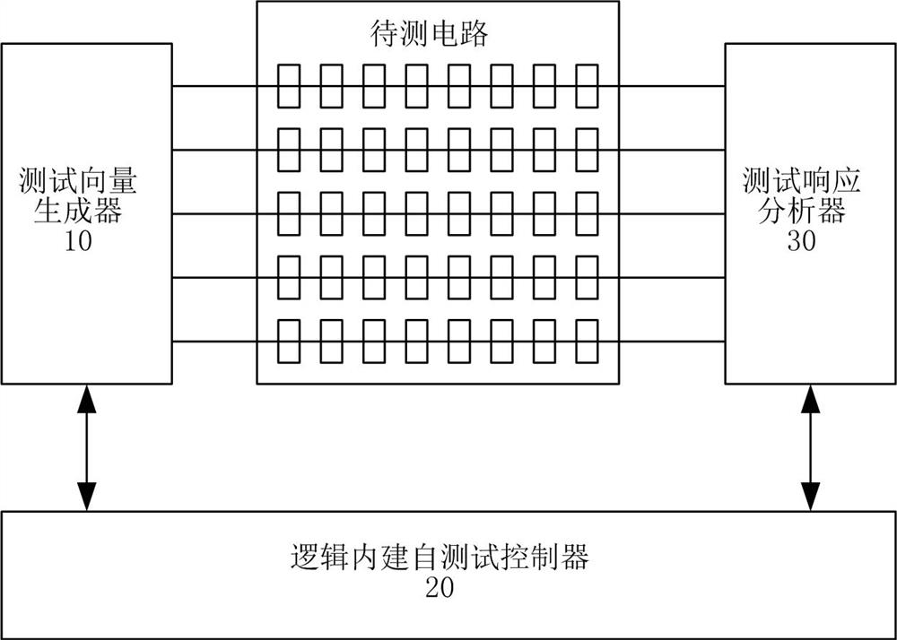
[0043] figure 1 It is a schematic structural diagram of a reset circuit test system for a logic built-in self-test according to the present invention, such as figure 1 As shown, the logic built-in self-test reset circuit test system of the present invention includes a test vector generator 10, a logic built-in self-test controller 20, and a test response analyzer 30, wherein,
[0044] Test vector generator 10, which generates reset test vector and pseudo-random test vector, accepts the instruction of logic built-in self-test controller 20, and outputs reset signal, clock signal, scan enable signal and scan vector output signal to the circuit to be tested .
[0045] Logic built-in self-test controller 20, it is connected with test vector generator 10, test response analyzer 30 respectively, controls test vector generator 10 to generate reset test vector and pseudo-random test vector, and the output of signal, control test response The analyzer 30 tests the circuit under test....
Embodiment 2
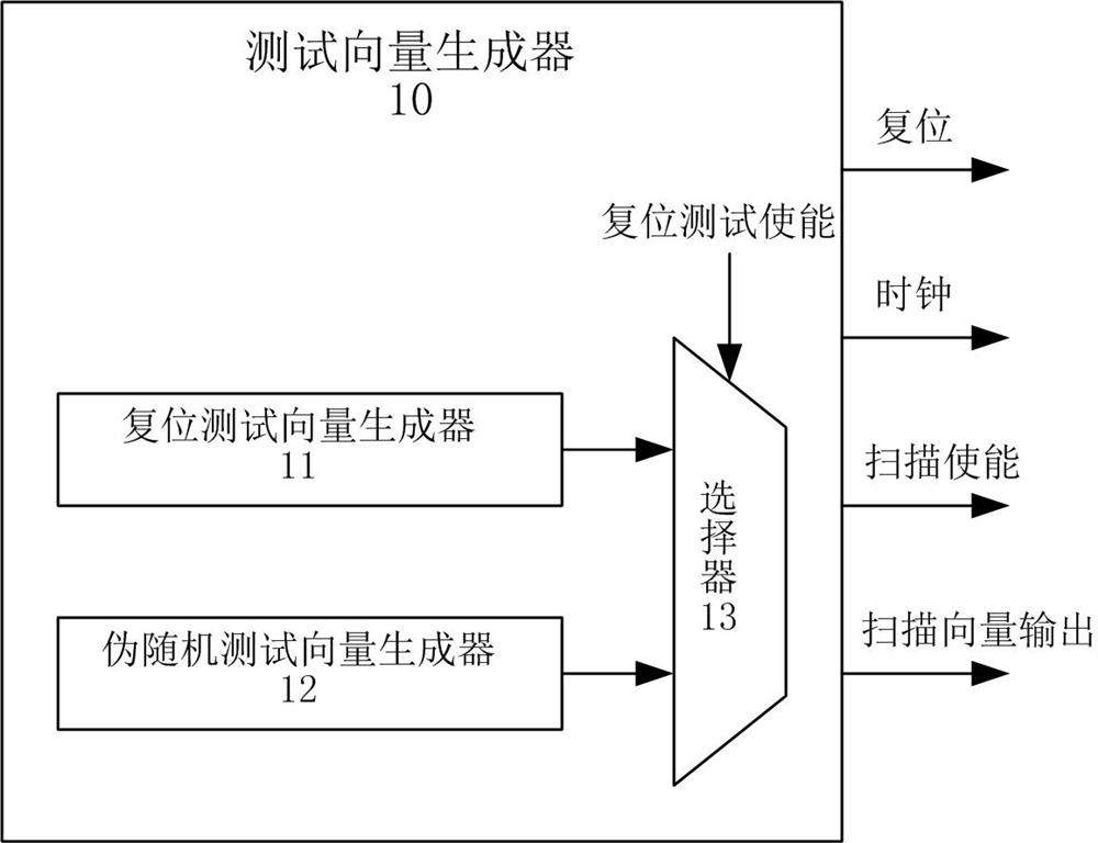
[0048] figure 2 It is a schematic diagram of a test vector generator according to the present invention, such as figure 2 As shown, the test vector generator of the present invention includes a reset test vector generator 11, a pseudo-random test vector generator 12, and a selector 13, wherein,
[0049] A reset test vector generator 11 that sends the generated reset test vector to one input terminal of the selector 13 .
[0050] A pseudo-random test vector generator 12, which sends the generated pseudo-random test vector to another input terminal of the selector 13.
[0051] The selector 13, which accepts the control of the reset test enable signal from the logic built-in self-test controller 20, selects the input reset test vector and the pseudo-random test vector, and resets the reset signal, the clock signal, the scan enable signal and The scan vector output signal is output to the circuit under test.
Embodiment 3
[0053] Figure 4 For the reset circuit test method flow chart of the logic built-in self-test according to the present invention, reference will be made below Figure 4 , the reset circuit testing method of the logic built-in self-test of the present invention is described in detail.
[0054] First, in step 401, the reset test enable is set to 1, and the reset test vector generator is selected.
[0055] In the embodiment of the present invention, the logic built-in self-test controller 20 sets the reset test enable of the selector 13 in the test vector generator 10 to 1, selects the output of the reset test vector generator, and performs the reset test vector test.
[0056] In step 402, set all reset test vectors to 1, set all scan vector outputs to 1, and perform reset test vector test.
[0057] In the embodiment of the present invention, such as image 3 As shown, in the scan shift (scan shift) stage: set the scan input (SI, the scan vector output signal generated by the ...
PUM
 Abstract
Description
Claims
Application Information