Hundred nanosecond laser pulse waveform distortion suppression system and method

A laser pulse and waveform distortion technology, applied in the laser field, can solve the problems of high cost and lack of flexibility, achieve the effect of visualization adaptability and suppressing optical nonlinear effects

Pending Publication Date: 2022-04-22
THE 23RD RES INST OF CHINA ELECTRONICS TECH GRP CORP
View PDF0 Cites 0 Cited by
  • Summary
  • Abstract
  • Description
  • Claims
  • Application Information

AI Technical Summary

Problems solved by technology

Changing the type or doping of the fiber matrix fundamentally solves the problem of uneven gain, and has good reliability, but it is only applicable to a small range of fixed bands; the static gain flattening filter is simple and easy to implement, and has a low Insertion loss, but like the first method, intelligently achieves the flatness of the static gain spectrum, and is seriously inflexible; dynamic gain balancing technologies include all-fiber acousto-optic tunable filters, cascaded liquid crystal optical harmonic equalization, and holographic polymer Various methods such as liquid crystal grating can realize real-time adjustment of multi-channel gain through corresponding control algorithms, which is highly intelligent, but its cost is too high, and it is not suitable for some small and medium-sized products

Method used


Image

  • Hundred nanosecond laser pulse waveform distortion suppression system and method
  • Hundred nanosecond laser pulse waveform distortion suppression system and method
  • Hundred nanosecond laser pulse waveform distortion suppression system and method

Examples


Embodiment 1

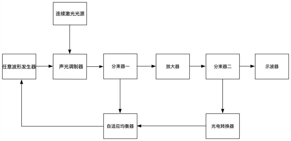
[0037] This embodiment, for example Figure 1 As shown, the acousto-optic modulator is connected to an arbitrary waveform generator, the other input terminal of the acousto-optic modulator is connected to the continuous laser light source, the acousto-optic modulator subsequently adjusts the trigger signal through the subsequent feedback signal and precompensates the output waveform. The beam splitter one receives the output pulsed laser of the acoustic and optical modulator, the beam splitter one connects the output terminal one to the adaptive equalizer, and the output terminal two is connected to the amplifier. The amplifier amplifies the pulsed laser, and the output is connected to the beam splitter two. The beam splitter two receives an amplified signal, and the output terminal one is connected to the photoelectric converter, the output terminal two is connected to the oscilloscope, the photoelectric converter converts the signal light of the output terminal one into an elect...

Embodiment 2

[0057] This embodiment, for example Figure 1 As shown, the acousto-optic modulator is connected to an arbitrary waveform generator, the other input terminal of the acousto-optic modulator is connected to the continuous laser light source, the acousto-optic modulator subsequently adjusts the trigger signal through the subsequent feedback signal and precompensates the output waveform. The beam splitter one receives the output pulsed laser of the acoustic and optical modulator, the beam splitter one connects the output terminal one to the adaptive equalizer, and the output terminal two is connected to the amplifier. The amplifier amplifies the pulsed laser, and the output is connected to the beam splitter two. The beam splitter two receives an amplified signal, and the output terminal one is connected to the photoelectric converter, the output terminal two is connected to the oscilloscope, the photoelectric converter converts the signal light of the output terminal one into an elect...

Embodiment 3

[0077] This embodiment, for example Figure 1 As shown, the acousto-optic modulator is connected to an arbitrary waveform generator, the other input terminal of the acousto-optic modulator is connected to the continuous laser light source, the acousto-optic modulator subsequently adjusts the trigger signal through the subsequent feedback signal and precompensates the output waveform. The beam splitter one receives the output pulsed laser of the acoustic and optical modulator, the beam splitter one connects the output terminal one to the adaptive equalizer, and the output terminal two is connected to the amplifier. The amplifier amplifies the pulsed laser, and the output is connected to the beam splitter two. The beam splitter two receives an amplified signal, and the output terminal one is connected to the photoelectric converter, the output terminal two is connected to the oscilloscope, the photoelectric converter converts the signal light of the output terminal one into an elect...


PUM


Abstract

The invention relates to the technical field of laser, in particular to a system and a method for suppressing waveform distortion of a hundred nanosecond laser pulse, which are characterized in that a trigger signal is set as a square wave to amplify laser, the pulse waveform of the amplified output laser is observed, and according to the sharpening degree of the output pulse laser, the waveform distortion of the hundred nanosecond laser pulse is suppressed. Pre-compensating an output waveform by using an arbitrary waveform generator through a tracing point; the acousto-optic modulator is connected with the light source at the same time, pulse laser of a corresponding waveform is obtained after a tracing point trigger signal of the arbitrary waveform generator is received, and finally near-flat-topped pulse output after laser amplification is achieved. According to the invention, the pulse waveform leading edge sharpening problem in the amplification process of the pulse laser is solved, the peak power of the pulse laser is reduced, the optical nonlinear effect of stimulated Brillouin scattering is inhibited, and the narrowing of the laser pulse width is limited.

Description

Technical field [0001] The present invention relates to the field of laser technology, specifically a suppression system and method for 100-nanosecond laser pulse waveform distortion. Background [0002] At present, two methods are mainly used to solve the waveform distortion problem caused by uneven gain in the amplification process of pulsed laser: one is to optimize the self-gain flatness of the design amplifier, and to improve the gain unevenness of the amplifier by changing the type or doping of the optical fiber matrix; the other is to introduce the gain flat technology, which can be divided into static gain flat filter and dynamic gain equalizer. Changing the type or doping of the fiber matrix fundamentally solves the problem of uneven gain, specific good reliability, but it is only suitable for a small range of fixed bands; static gain flat filter is simple and easy, while having low insertion loss, but as with the first method, intelligently achieve the flatness of the ...

Claims


Application Information

Patent Timeline
Patent Type & Authority Applications(China)
IPC IPC(8): H01S3/13H01S3/00
CPCH01S3/0085H01S3/0057H01S3/1305
Inventor 吴洋邢美术林兆培丁亚茜戚伟
Owner THE 23RD RES INST OF CHINA ELECTRONICS TECH GRP CORP
Why Eureka
Try Eureka