Industrial fluidized bed reactor

A fluidized bed reactor and reactor technology, applied in chemical instruments and methods, aerobic process treatment, biological water/sewage treatment, etc., can solve the problem that it is difficult to ensure normal fluidization inside the reactor and the fluidization effect is not ideal. , the reduction of gas-liquid mass transfer efficiency, etc., to achieve the effect of improving oxygen utilization rate, satisfying optimal matching, and improving fluidization state

Pending Publication Date: 2022-05-03
CHINA PETROLEUM & CHEM CORP +1
View PDF7 Cites 1 Cited by
  • Summary
  • Abstract
  • Description
  • Claims
  • Application Information

AI Technical Summary

Problems solved by technology

At present, most of the domestic biological fluidized bed reactors are in the form of central airlift, and there is a large dead angle at the connection between the guide tube and the guide partition, the fluidization effect is not ideal, and with the increase of the processing capacity, The volume of the reactor is also getting larger and larger, and it is difficult to ensure the normal fluidization inside the reactor with this form of internal component arrangement, the fluidization effect is not ideal, and the gas-liquid mass transfer efficiency is reduced

Method used


Image

  • Industrial fluidized bed reactor
  • Industrial fluidized bed reactor

Examples


Embodiment 1

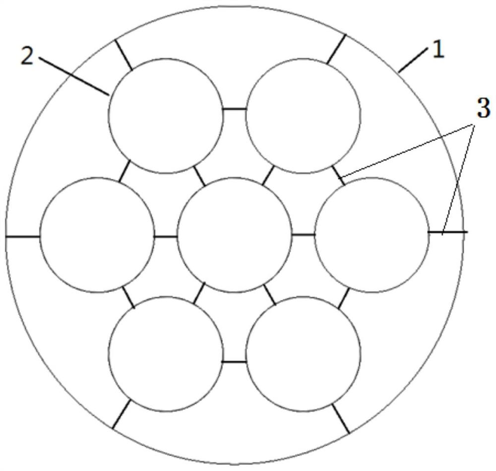
[0023] A reactor has a total height of 2m and a diameter of 1m, see figure 1 , the reactor includes a reactor shell 1 , a draft tube 2 and a support plate 3 .

[0024] The height of the inner guide tube is 1.5 meters, the height-to-diameter ratio of the guide tube 2 is 6-8, and the annular gap ratio is 0.8-1.

[0025] The interior of the reactor is divided into an area. The diameter of the guide tube 2 is 250mm, and it is arranged in a manner of one in the center and six evenly distributed on the circumference. A gas distributor (not shown) is arranged directly under each guide tube 2 .

[0026] The reactor shell 1, the guide tube 2 and the support plate 3 are made of carbon steel or stainless steel, and the guide tubes 2 and the reactor shell 1 are connected through the support plate and welded or bolted.

[0027] The effective volume of the device is 2.8m 3 , the processing capacity is 0.2~0.5m 3 / h, aerobic biological fluidized bed reactor influent COD: 1500~2000mg / L, BO...

Embodiment 2

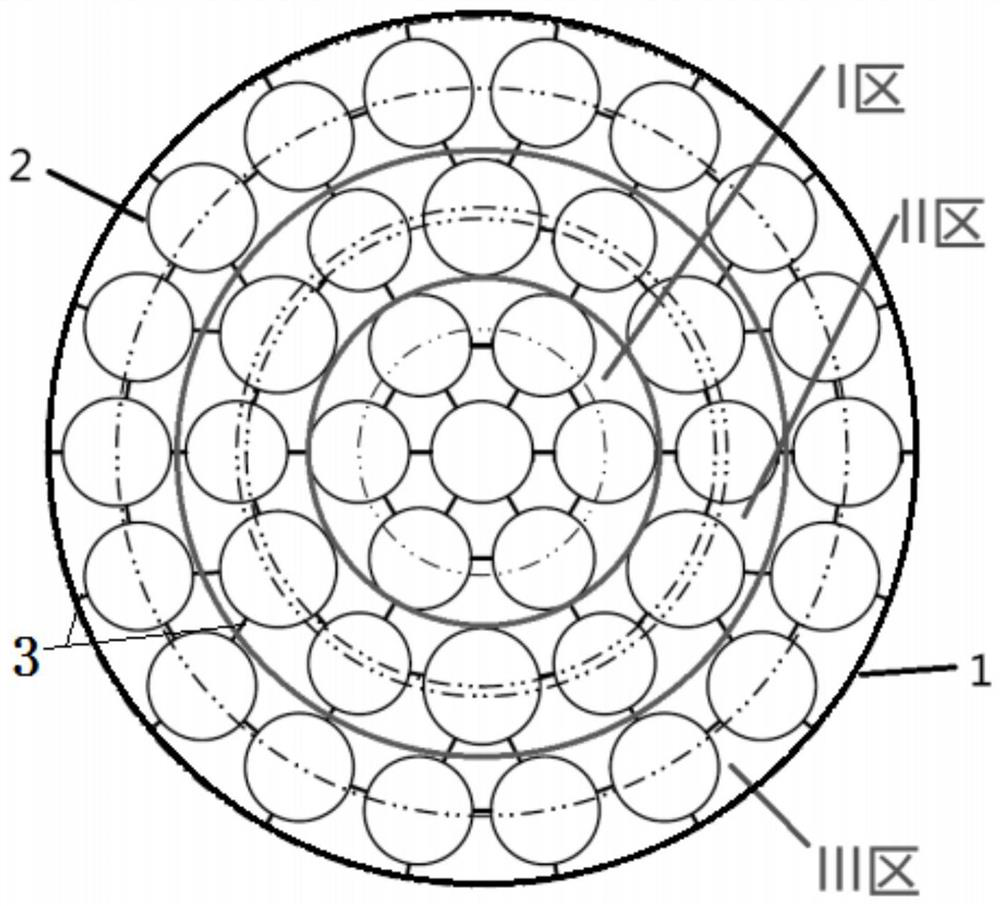
[0029] see figure 2 , the total height of the reactor is 12m, the diameter is 10m, the height of the inner guide tube 2 is 9 meters, the height-to-diameter ratio of the guide tube 2 is 7, and the annulus ratio is 0.9.

[0030] The diameter of the guide tube in Zone I is 1.2m, and it is arranged in a way of one in the center and six evenly distributed on the circumference, and the diameter of the distribution circle is 3m.

[0031] Diversion cylinders in Zone II There are two types of guide cylinders with diameters of 1.2m and 1.4m, and the intervals are distributed on the circumference with diameters of 5.7m and 5.9m. The number of guide cylinders in Zone II is 12.

[0032] The diameter of the diversion tubes in Zone III is 1.3m, distributed in a circle, the diameter of the distribution circle is 8.8m, and the number of guide tubes in Zone III is 18.

[0033] The device has an effective volume of 1000m3 and a processing capacity of 130m 3 / h, aerobic biological fluidized be...


PUM

PropertyMeasurementUnit
heightaaaaaaaaaa
aspect ratioaaaaaaaaaa

Abstract

The invention discloses an industrial fluidized bed reactor which comprises a reactor shell, a plurality of guide cylinders and a plurality of gas distributors arranged at the bottoms of the guide cylinders, the axes of the guide cylinders are parallel, and the guide cylinders are arranged in the reactor shell at intervals. And the guide cylinders as well as the guide cylinders and the reactor shell are connected by adopting support plates through welding or bolts. By reasonably designing the arrangement mode of the guide cylinders, the oxygen utilization rate is improved, the fluidization state in the reactor is improved under the condition that the overall height of the reactor is not changed, the optimal matching of oxygen and air inflow required by aerobic biochemistry of microorganisms is met, the air consumption is reduced, and the mass transfer efficiency of the reactor is improved.

Description

technical field [0001] The invention belongs to the field of biological fluidized bed design for waste water and sewage treatment, and specifically relates to an industrial fluidized bed reactor. Background technique [0002] The aerobic biological fluidized bed reactor is widely used in the field of wastewater treatment. The reactor has the advantages of simple structure, low energy consumption, small shear stress, and good mixing. It is currently the most widely used biological reaction equipment. In terms of engineering design, how to further optimize the design of the internal components of the aerobic biological fluidized bed, strengthen the mixing and mass transfer of the reactor, and make the COD removal faster, more efficient, and lower consumption is the current research on the sewage biological treatment technology of the aerobic biological fluidized bed the key of. In the design of aerobic biological fluidized bed reactor, the circulating liquid velocity and gas ...

Claims


Application Information

Patent Timeline
Patent Type & Authority Applications(China)
IPC IPC(8): C02F3/08
CPCC02F3/085C02F2203/006C02F2209/08Y02W10/10
Inventor 邓睿赵海云田小峰石蓉芸李培超
Owner CHINA PETROLEUM & CHEM CORP
Why Eureka
Try Eureka