
Heart valve repairing device

A heart valve and metal tube technology, applied in the field of medical devices, can solve the problems of large rigid ring delivery diameter, poor support and forming effect, high reoperation rate, etc., and achieve the effect of convenient operation, high support strength and high fault tolerance rate

Pending Publication Date: 2022-05-10
SHANGHAI HEALING MEDICAL DEVICES CO LTD
View PDF0 Cites 0 Cited by
  • Summary
  • Abstract
  • Description
  • Claims
  • Application Information

AI Technical Summary

Problems solved by technology

Dilation of the mitral valve annulus impedes the valve's ability to distort the normal shape of the valve orifice
The material of the rigid ring is relatively hard, not easy to bend, and cannot achieve coordinated movement with the cardiac cycle
The flexible ring is closer to the physiological activity of the normal mitral valve ring, and has less impact on the left ventricular function, but the support and shaping effect is poor. Mitral regurgitation recurrence is prone to occur after surgery, and the reoperation rate is relatively high.
[0004] Before the implementation of mitral annuloplasty, the forming ring needs to be adjusted in a straight line and loaded into the forming ring loading cavity of the delivery system. The rigid ring is generally loaded into the forming ring loading cavity in a folded structure, but the folded structure The delivery diameter of the rigid ring is relatively large, which requires a higher size of the forming ring loading cavity; while the flexible ring has a smaller delivery diameter, but its supporting and forming effects are poor, and mitral regurgitation recurrence is prone to occur after surgery

Method used


Image

  • Heart valve repairing device
  • Heart valve repairing device
  • Heart valve repairing device

Examples


Embodiment Construction

[0089] The technical solutions of the present invention will be clearly and completely described below in conjunction with the accompanying drawings. Apparently, the described embodiments are some of the embodiments of the present invention, but not all of them. Based on the embodiments of the present invention, all other embodiments obtained by persons of ordinary skill in the art without making creative efforts belong to the protection scope of the present invention.

[0090]In the description of the present invention, it should be noted that the terms "center", "upper", "lower", "left", "right", "vertical", "horizontal", "inner", "outer" etc. The indicated orientation or positional relationship is based on the orientation or positional relationship shown in the drawings, and is only for the convenience of describing the present invention and simplifying the description, rather than indicating or implying that the referred device or element must have a specific orientation, o...


PUM


Abstract

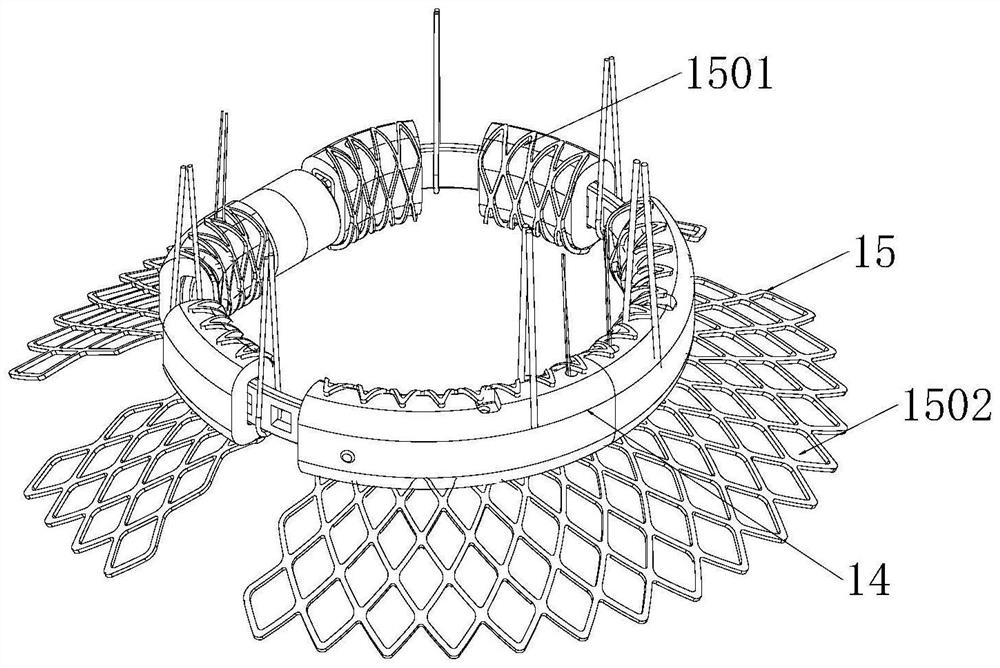
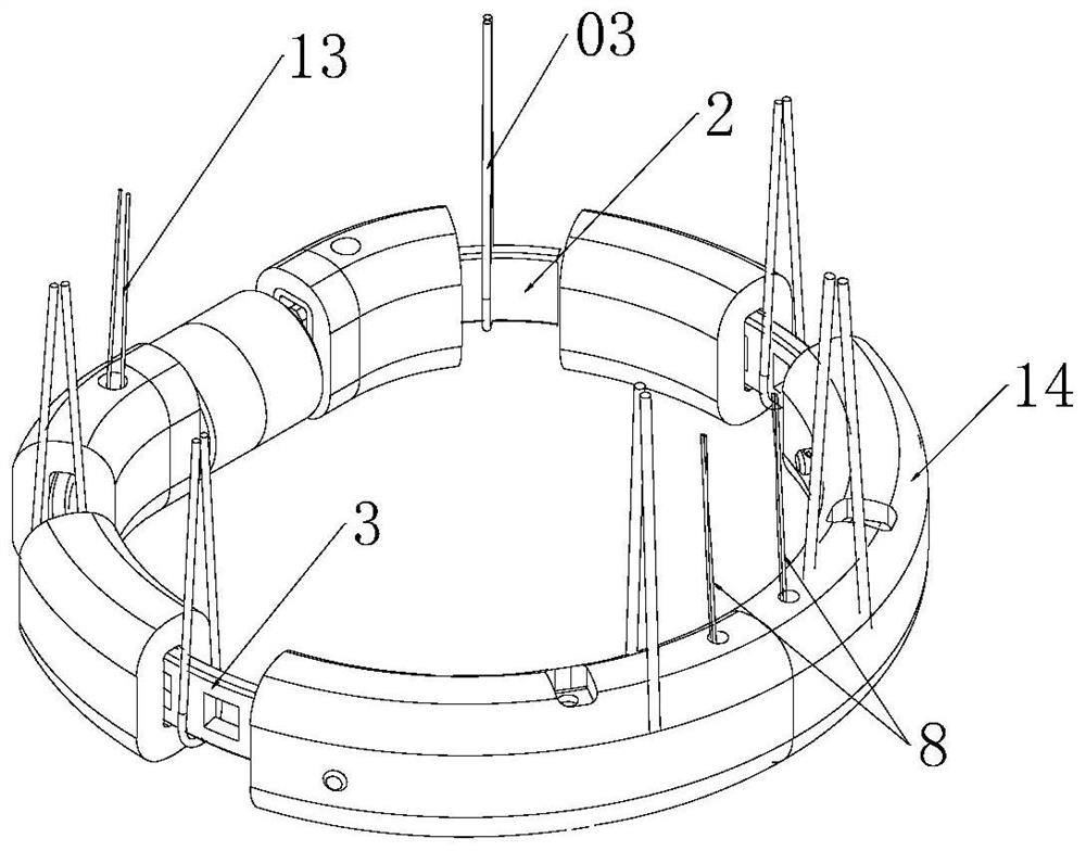
The invention discloses a heart valve repairing device, which comprises a forming ring body and a contraction traction line, and is characterized in that the forming ring body comprises at least two metal strips, end part metal tubes arranged at the end parts of the metal strips in a sleeving manner, and joint part metal tubes arranged between the two adjacent metal strips in a sleeving manner; a first traction hole is formed in one end of the metal strip, and a second traction hole is formed in the connecting part metal pipe. And the contraction traction wire is wound on the first traction hole and the second traction hole so as to connect the metal strip and the connecting part metal tube. The two end metal pipes are connected through a buckle assembly. The contraction traction wire is wound on the first traction hole and the second traction hole to connect the metal strip and the connecting part metal pipe, and the two end metal pipes are connected through the buckle assembly to enable the forming ring body to be connected end to end to form the annular structure, so that compared with a rigid folding type forming ring structure, the conveying diameter is smaller, and the conveying efficiency is improved. The overall strength is slightly lower than that of a rigid folding structure, but the required supporting strength can be met.

Description

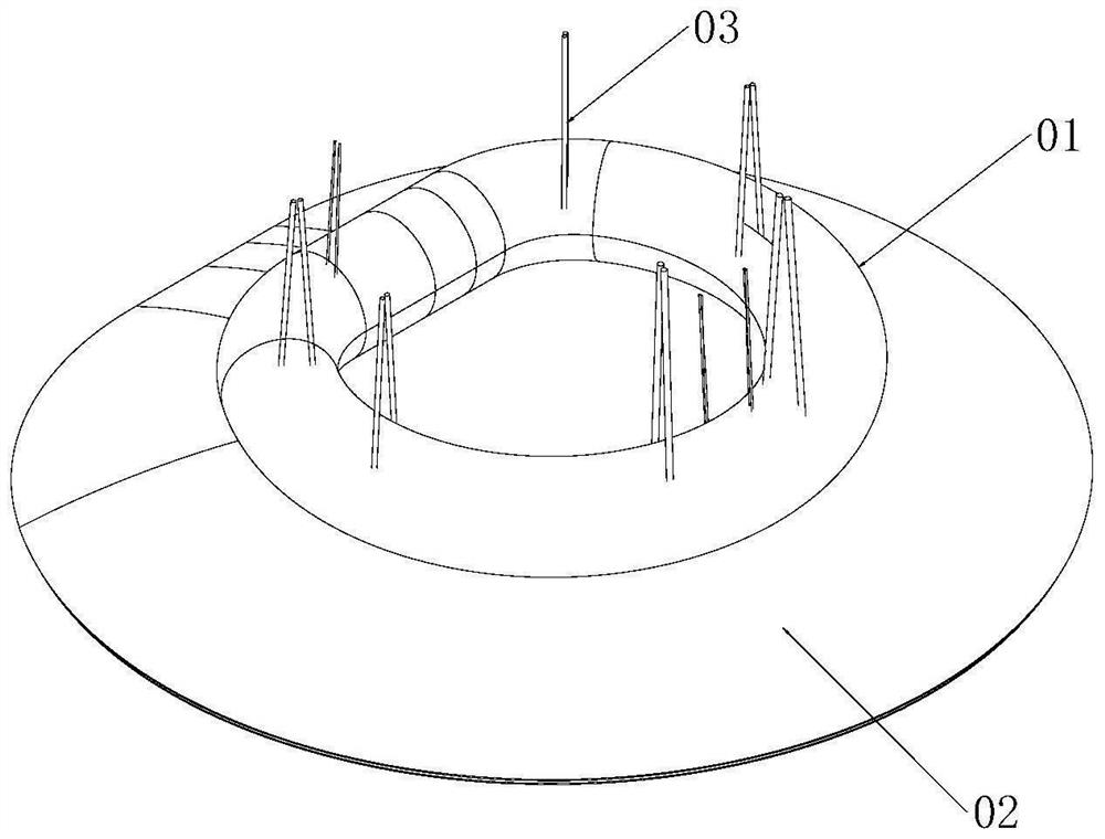
technical field [0001] The invention relates to the technical field of medical instruments, in particular to a heart valve repair device. Background technique [0002] Mitral valvuloplasty is the treatment of mitral regurgitant heart valve disease by implanting an artificial mitral annuloplasty ring. Prosthetic mitral annuloplasty rings are used as part of mitral annuloplasty to assist in the correction of heart valve defects such as mitral regurgitation. The mitral valve includes the mitral annulus, leaflets, papillary muscles, and chordae. Mitral regurgitation is the backflow of blood from the left ventricle through the mitral valve to the left atrium when the left ventricle contracts. Dilation of the mitral valve annulus impedes the valve's ability to distort the normal shape of the valve orifice. [0003] For the surgical treatment of mitral regurgitation, mitral valvuloplasty has obvious advantages compared with mitral valve replacement in terms of survival rate, val...

Claims


Application Information

Patent Timeline
Patent Type & Authority Applications(China)
IPC IPC(8): A61F2/24
CPCA61F2/24A61F2/2442A61F2/2454A61F2/2463
Inventor 陈晓黄韬张铭宇刘冰冰李阳陈韵岱陆树洋
Owner SHANGHAI HEALING MEDICAL DEVICES CO LTD
Learn More