CO2 direct air trapping system and method based on wet regeneration adsorption material

An adsorption material, wet regeneration technology, applied in the field of DAC, can solve the problems of reduced purity, small storage capacity, solid powder pollution gas, etc.

Pending Publication Date: 2022-05-10
霖和气候科技(北京)有限公司
View PDF11 Cites 1 Cited by
  • Summary
  • Abstract
  • Description
  • Claims
  • Application Information

AI Technical Summary

Problems solved by technology

However, the drying process of this technical solution uses anhydrous calcium chloride, which is easy to cause corrosion to the equipment, and the solid powder may also pollute the gas; the material is humidified through the wet air flow, the speed is slow and the infiltration effect is not obvious; a single ta...

Method used


Image

  • CO2 direct air trapping system and method based on wet regeneration adsorption material
  • CO2 direct air trapping system and method based on wet regeneration adsorption material
  • CO2 direct air trapping system and method based on wet regeneration adsorption material

Examples


Embodiment 1

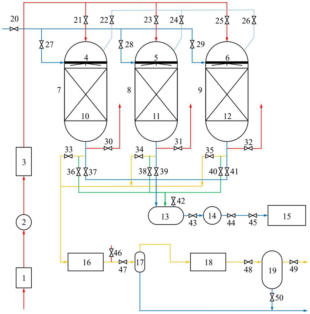
[0081] Using the CO based on the wet regeneration adsorption material described in the above technical scheme 2 Direct air capture system, the specific working process is as follows:

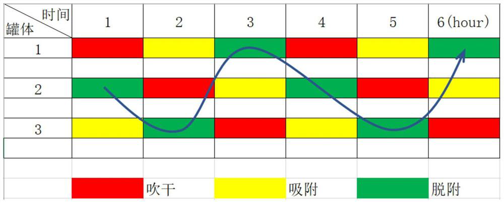
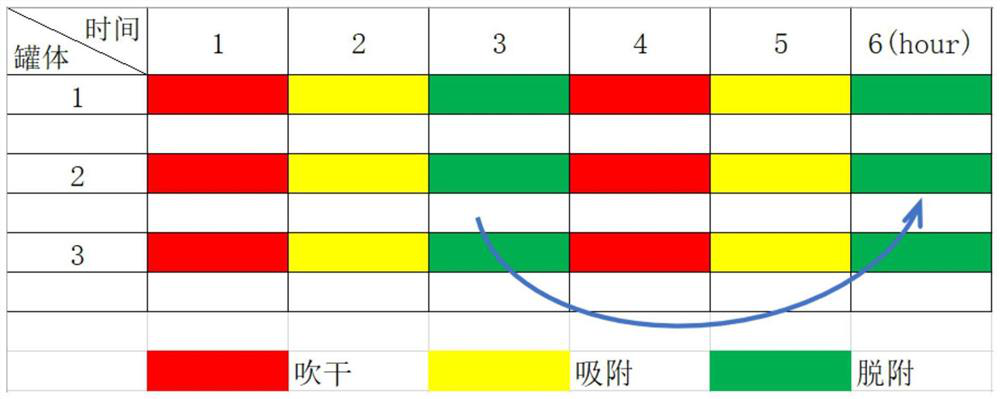
[0082] CO 2 Adsorbent material drying: Taking the first catch tank 7 as an example, the air in the environment (CO 2 Concentration is 0.04%) at 2300m 3 After the flow rate per hour is heated by the heat source 1 (40°C ~ 50°C), it is sent to the dehumidification device 3 by the fan 2, so that the relative humidity of the air is reduced to the range of 20% ~ 30%; the heated and dehumidified air passes through the valve 21 Enter the first catch tank 7, blow through the first group of CO from top to bottom 2 The adsorption material 10 thus plays a drying role, and then is discharged into the atmosphere through the valve 30; the whole drying process lasts for 1 hour.

[0083] CO 2 Adsorption: Group 1 CO 2 After the adsorption material 10 is dried for 1 hour, the heat source 1 can be turned off ...

Embodiment 2

[0094] Using the CO based on the wet regeneration adsorption material described in the above technical scheme 2 Direct air capture system, the specific working process is as follows:

[0095] CO 2 Adsorbent material drying: vacuum drying is adopted, the initial stage is mainly to extract air, and the rest of the stage is to extract water vapor. Taking the first catch tank 7 as an example, the vacuum pump 16 first removes the air in the first catch tank 7 through the valve 33 and discharges it from the valve 46, so that the pressure in the tank drops below 2kPa (it should be noted that after vacuumizing While drying, the CO in the capture tank can be 2 The adsorption material is properly and continuously heated, so that the moisture inside the material diffuses into the low-pressure air on the surface through the pressure difference or concentration difference, and then is sucked away by the vacuum pump to further increase the drying speed); the subsequent process mainly remo...


PUM


Abstract

The invention provides a CO2 direct air trapping system based on a wet regeneration adsorption material, which comprises a plurality of groups of trapping devices connected in parallel, the top of each trapping device is provided with an air inlet, the upper part of each trapping device is provided with a liquid phase inlet and is communicated with a spraying device arranged inside, the lower part of each spraying device is provided with a CO2 adsorption material, and the bottom of each spraying device is provided with a material outlet; the material outlet is respectively connected with the CO2 adsorption material drying gas phase branch, the mixed gas branch and the liquid phase branch; the dehumidifying device, the fan and the heat source are respectively connected with air inlets of the plurality of groups of trapping devices which are connected in parallel; the vacuum pump, the gas-liquid separator, the compressor and the CO2 storage tank are respectively connected with the mixed gas branches of the plurality of groups of trapping devices which are connected in parallel; the liquid storage tank, the water pump and the water tank are respectively connected with the liquid phase branches of the plurality of groups of trapping devices which are connected in parallel. The system can realize the following beneficial effects: the regeneration energy consumption and cost of the adsorption material are reduced; the space utilization rate is improved; the continuous capture and storage of CO2 are realized; cO2 with high concentration is output; and the CO2 gas is not polluted.

Description

technical field [0001] The invention relates to the technical field of DAC, more specifically, relates to a CO 2 Direct air capture systems and methods. Background technique [0002] At present, the main carbon capture technologies are divided into pre-combustion capture, post-combustion capture and oxygen-enriched combustion capture. 2 concentrated capture technology. In fact, about 30-50% of the world's annual CO 2 From distributed emission sources such as transportation, residential building heat, and small factories, CO 2 Direct air capture technology can be used as an effective compensation for centralized capture technology, but there is currently a lack of low energy consumption and continuous capture of CO in the air. 2 system. [0003] DAC (Direct air capture; capture CO directly from the air 2 technology) capture is different from the traditional power plant centralized capture technology, which does not require the captured CO 2 Transported to the storage s...

Claims


Application Information

Patent Timeline
IPC IPC(8): B01D53/02
CPCB01D53/02B01D2257/504B01D2259/40083
Inventor 李锋王凯张继朱亮亮陈曦王珮骅
Owner 霖和气候科技(北京)有限公司
Why Eureka
Try Eureka