
Patsnap Eureka
For R&D, Patsnap Eureka makes reading and utilizing patents & technical documents easy.
Patsnap Eureka AIR
Designed for self-driven R&D workflows. Generate viable solutions, solve complex R&D challenges, empower your innovation with AI.

Patsnap Eureka Materials
Designed for material experts only. Revolutionize your material R&D, from search, analyze, to developing new materials.

TechResearch
Generate reliable direction feasibility study reports for your R&D in just a few steps.

TechSeek
Discover and master advanced knowledge NOW. Basics, ideas, possibilities, all at once.

TechMind
As an expert in R&D Theories, TechMind can generates customized viable solutions instantly.

TechRisk
Analyze your overall solution with one click, know your potential R&D risks in advance.

TechMonitor
Get weekly tech updates, stay abreast of the latest tech innovations and key insights.
Method and device for detecting alkane content in natural gas
A detection method and technology of natural gas, applied in the direction of color/spectral characteristic measurement, etc., can solve the problems of complex equipment and instrument requirements, long analysis cycle, etc., and achieve the effect of fast detection speed, high accuracy and strong applicability
- Summary
- Abstract
- Description
- Claims
- Application Information
AI Technical Summary
Problems solved by technology
Method used
Image

Examples
Embodiment 1
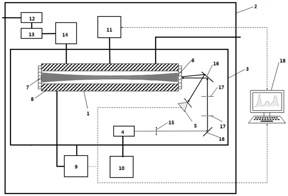
[0054] This embodiment provides a detection device for methane, ethane and propane content in natural gas, the structure is as follows figure 1 As shown, it includes an outer shell 2 and an inner shell 3 , and the inner shell 3 is provided with an optical cavity 1 , a laser 4 and a detector 5 . Both ends of the optical cavity 1 are equipped with a first Heriott reflector 6 and a second Heriott reflector 7, wherein the first Heriott reflector 6 has a central hole, and the laser 4 emits The laser light enters the optical cavity 1 through the central hole of the first Heriott mirror 6 through the lens 15 , two mirrors 16 and two groups of diaphragms 17 , and the outgoing light signal is received by the detector 5 .
[0055] The surface of the optical cavity 1 is covered with a heating insulation layer 8, and the temperature control module 9 arranged in the outer casing 2 heats the heating insulation layer 8 and the inner casing 3, and a laser driver 10 connected to the laser 4 is...
Embodiment 2
[0059] In this embodiment, the detection device in Embodiment 1 is used to detect the content of methane, ethane, propane, butane and pentane in the natural gas to be tested. Specific steps are as follows:
[0060] (1) Turn on the air pump and the heating preprocessor, the temperature control module heats the heating insulation layer of the cavity and the inner shell 19 to 50°C and 30°C respectively, and the laser part modulates the current of the laser through an external function generator, A triangular wave with a scanning frequency of 7Hz is used to modulate the driving current of the laser, so that the frequency of the laser output laser linearly scans CH 4 at the first wavelength v 1 The wavenumber of the laser is 6060.5cm -1 Near the transition line, that is, the wavelength is 1.65 μm;
[0061] (2) the pure CH 4 Pass a certain flow into the optical cavity, record the temperature in the experiment as 50°C and the pressure as 50torr, and measure the value of light ene...
PUM
 Abstract
Description
Claims
Application Information
 - R&D Engineer
- R&D Manager
- IP Professional
- Industry Leading Data Capabilities
- Powerful AI technology
- Patent DNA Extraction
Browse by: Latest US Patents, China's latest patents, Technical Efficacy Thesaurus, Application Domain, Technology Topic, Popular Technical Reports.
© 2024 PatSnap. All rights reserved.Legal|Privacy policy|Modern Slavery Act Transparency Statement|Sitemap|About US| Contact US: help@patsnap.com