Resin laser radar

A laser radar and resin technology, applied in the field of mechanical equipment, can solve the problems of easy fracture and separation between structures, the inability to occur optical parts, and dislocation in time, so as to facilitate maintenance and calibration work, facilitate shock absorption and protection work, and avoid Fracture effect

Pending Publication Date: 2022-05-10
陈龙龙
View PDF0 Cites 0 Cited by
  • Summary
  • Abstract
  • Description
  • Claims
  • Application Information

AI Technical Summary

Problems solved by technology

[0004] In the existing lidar structure, the radar generating structure and the main support usually only have a rotational connection, and do not have any relative movement in other directions. Therefore, when the radar is subjected to impact forces in different directions , it is easy to break and separate between the structures, even if there is no fracture, the internal optical components are easy to be dislocated; in addition, the traditional lidar does not have the function of self-checking the internal optical parts, so the staff cannot timely generate optical components. Parts have been misplaced

Method used


Image

  • Resin laser radar
  • Resin laser radar
  • Resin laser radar

Examples


Embodiment 1

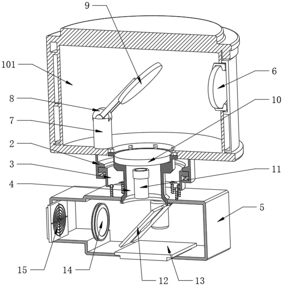
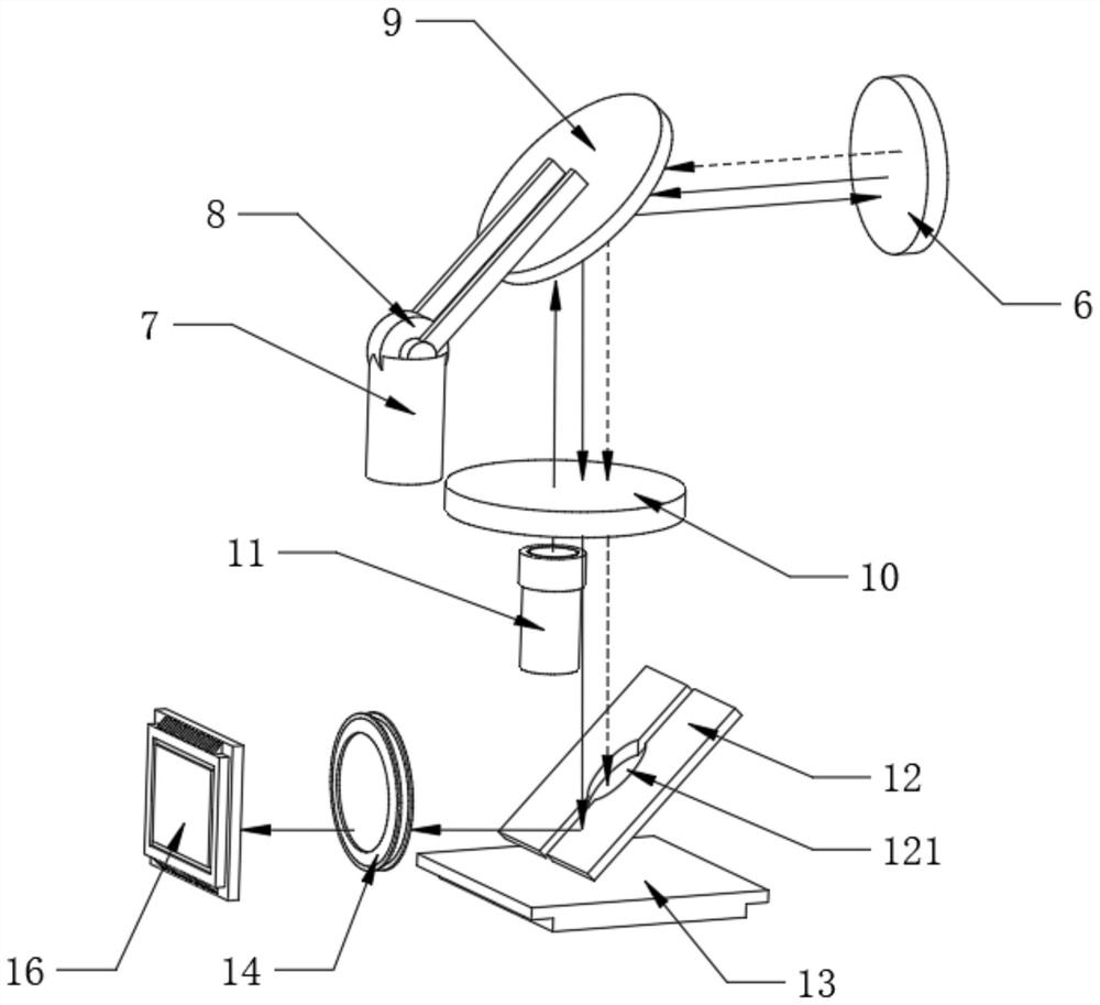
[0037] Refer to attached figure 2 The radar generation top case 1 also includes a top case 101, the inner side of the top case 101 is fixedly embedded with a light-transmitting mirror 6, and the inner side of the top case 101 is fixedly installed with a servo motor 7, and the top of the servo motor 7 is assembled There is a circular grating 8, the end of the circular grating 8 is fixedly assembled with a bevel mirror 9, the inner top of the rotating tube body 4 is fixedly assembled with an optical rotary encoder 10, and the inside of the bottom frame 5 is fixedly installed directly below the corresponding optical rotary encoder 10 There is a receiver 13, the inside of the rotating tube body 4 is located below the optical rotary encoder 10, and a laser source 11 is fixedly installed. The light beam of the detected object enters the inside of the radar generating top shell 1 through the light-transmitting mirror 6, and passes through the inclined mirror 9. Refraction, the light b...

Embodiment 2

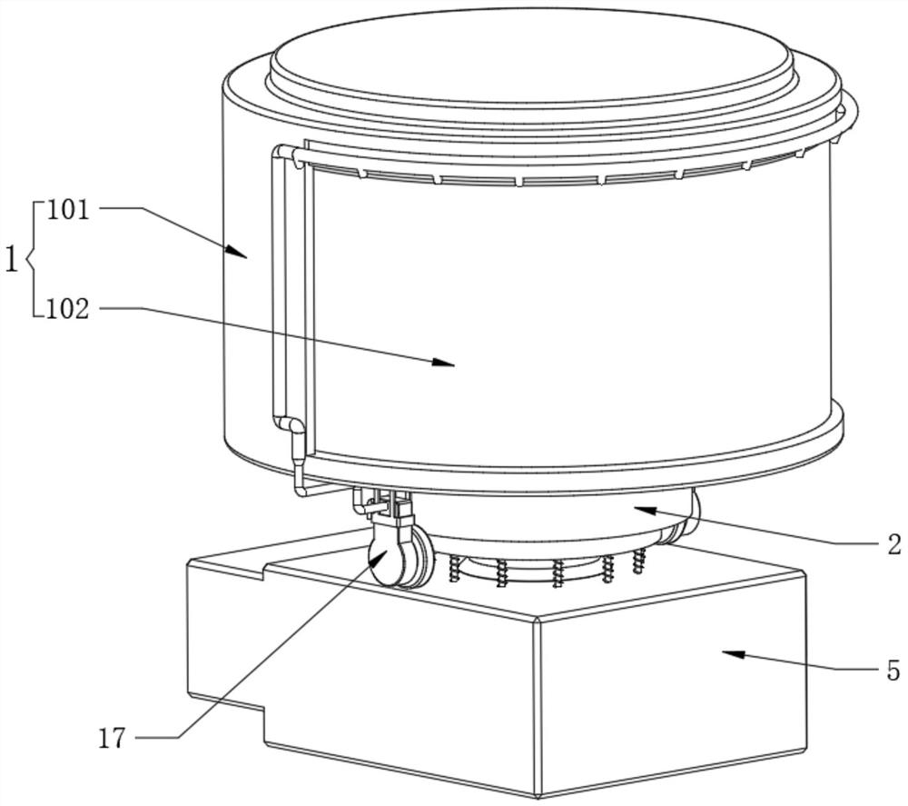
[0042] Refer to attached figure 1 with Figure 4 One side of the outer wall of the top case 101 is fixedly provided with a launch window 102 , and the inner wall of the opening on the lower surface of the top case 101 is equidistantly provided with non-penetrating slots 103 .

[0043] Refer to attached Figure 4 The rotating tube body 4 also includes a rotating tube 401, the top outer wall of the rotating tube 401 is equidistantly fixed with protrusions 402, and the protrusions 402 are slidably embedded in the corresponding non-penetrating slot 103, and the height dimension of the non-penetrating slot 103 The thickness of the protrusion 402 is greater than that of the protrusion 402 , so that there is a relative movement between the top case 101 and the rotating tube 401 in the longitudinal direction.

[0044] Refer to attached Figure 4 , the outer wall of the bottom end of the rotating tube 401 is located at the inside of the base 5 and is equidistantly fixedly provided w...

Embodiment 3

[0050] Refer to attached Figure 7 The linkage clearing assembly 17 also includes an air injector 1701 , the top ends of the two air injectors 1701 are fixedly mounted with mounting brackets 1702 , and the two mounting brackets 1702 are respectively fixedly connected to both sides of the lower surface of the top case 101 .

[0051] Refer to attached Figure 8 , one side of the bottom end of the air injector 1701 is rotatably equipped with a fitting wheel 1707, and the fitting wheel 1707 fits with the upper surface of the base frame 5, and the inner bottom of the air injector 1701 is equipped with a crankshaft 1708 for rotation, and The wheel 1707 is fixedly connected with the crankshaft 1708, and the end of the crankshaft 1708 is connected with a deflection rod 1709 for rotation, and the end of the deflection rod 1709 is connected with a piston 1710 for rotation, and the piston 1710 is slidably installed inside the air injector 1701. While the top shell 1 is rotating, the fit...


PUM


Abstract

The invention belongs to the technical field of mechanical equipment, and particularly relates to a resin laser radar which comprises a bottom machine base, a switching assembly is fixedly arranged on the upper surface of the bottom machine base, the outer surface of the top end of the switching assembly is movably sleeved with a low pipe body, and the top end of the low pipe body is fixedly connected with a radar generation top shell. And a rotating pipe body is rotatably arranged on the upper surface of the bottom machine base and located in the adapter assembly, the top end of the rotating pipe body is slidably connected with the radar generating top shell in a clamped mode, and a linkage resistance clearing assembly is fixedly arranged on the outer wall of the radar generating top shell. Whether the optical parts in the laser radar deviate or not can be automatically diagnosed, the device has a part self-checking function, in addition, relative movement in multiple directions exists between the structures, the structure is flexible, damping protection work of the internal optical parts is facilitated, finally, foreign matter on the surface of an emission window can be automatically cleaned, and normal use of the radar is guaranteed.

Description

technical field [0001] The invention belongs to the technical field of mechanical equipment, and in particular relates to a resin laser radar. Background technique [0002] Lidar is a radar system that emits laser beams to detect the position, speed and other characteristic quantities of the target; its working principle is to transmit a detection signal (laser beam) to the target, and then receive the signal reflected from the target (target echo) ) is compared with the transmitted signal, and after proper processing, the relevant information of the target can be obtained, such as target distance, azimuth, height, speed, attitude, and even shape parameters, so as to detect, track and identify aircraft, missiles and other targets ; It is composed of a laser transmitter, an optical receiver, a turntable and an information processing system. The laser converts electrical pulses into optical pulses and emits them. The optical receiver then restores the optical pulses reflected ...

Claims


Application Information

Patent Timeline
Patent Type & Authority Applications(China)
IPC IPC(8): G01S17/02G01S7/481B08B3/02
CPCG01S17/02G01S7/481B08B3/02
Inventor 陈龙龙
Owner 陈龙龙
Why Eureka
Try Eureka