Low negative pressure injection deep hole continuous sampling system and sampling method

A sampling system, low negative pressure technology, applied in the direction of earthwork drilling, wellbore/well components, gas discharge, etc., can solve the problem of large gas analysis loss, etc., and achieve the effect of saving operation time, convenient operation, and low flow rate

Active Publication Date: 2022-06-07
CHINA UNIV OF MINING & TECH
View PDF9 Cites 0 Cited by
  • Summary
  • Abstract
  • Description
  • Claims
  • Application Information

AI Technical Summary

Problems solved by technology

In recent years, many scholars have carried out a series of researches on the negative pressure sampling of coal seams. The Chinese invention patent published on August 6, 2014 has a publication number of CN103967437A "A Downhole Pressure Air Fixed-point Sampling Device and Sampling Process" , it realizes negative pressure ejection sampling through double-walled drill rods matching the air outlet inclined hole on the outer wall of the drill bit and the air inlet at the top of the drill bit; a Chinese patent published on October 7, 2009 with a publication number of CN201321859Y "a kind of Borehole injection sampling device", which is to directly suck the coal sample into the sample collection tank by setting the ejector at the end of the drill pipe, so as to realize the collection of coal samples. The problem of gas analysis loss in slag process

Method used


Image

  • Low negative pressure injection deep hole continuous sampling system and sampling method
  • Low negative pressure injection deep hole continuous sampling system and sampling method
  • Low negative pressure injection deep hole continuous sampling system and sampling method

Examples


Embodiment

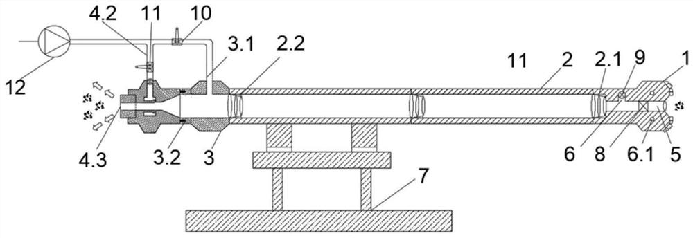
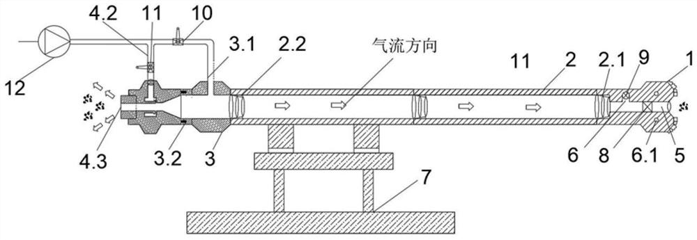
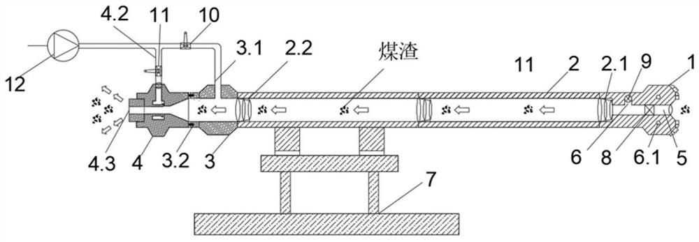
[0108] ①When the sampling drill bit 1 drills to the sampling point A, close the manual valve I10, open the manual valve II11, the air supply pump 12 provides compressed air flow, and the compressed air flows through the air supply pipeline 4.2 to the compressed air inlet 4.1 and then flows to the air amplifier 4 Negative pressure air flow is formed inside, compressed air volume Q 缩 is 100L / min, the diameter d of the exhaust slag discharge port of the air amplifier 4 is 4.3 出 0.1m, the air inlet of the air amplifier is 4.4 in diameter d 进 is 0.15m, the Q measured by the downhole field test 出 for Q 缩 20 times as 2×10 4 L / min, the n value is equal to 10, the airflow velocity v of the exhaust slag discharge port 4.3 出 4.24×10 3 m / s;

[0109] ②Under the action of the air amplifier 4, a negative pressure environment is formed in the drill pipe 2, and the negative pressure airflow flows into the sampling hole 5 of the sampling drill bit 1. Under the action of the negative press...


PUM


Abstract

According to the low-negative-pressure injection deep hole continuous sampling system and method, a sampling hole is formed in a sampling drill bit and communicated with a hollow rod of a drill rod, an exhaust hole is formed in the rear side wall of a cavity in the sampling drill bit, and exhaust inclined holes are evenly distributed in the outer wall of the sampling drill bit and communicated with the exhaust hole; the matched water braid is of a hollow structure, an air-water pipeline is arranged on the side wall of the matched water braid, and the tail of the matched water braid is connected with the air amplifier. The air amplifier is of a hollow structure and is communicated with the matched water braid through an air inlet, a compressed air inlet nozzle is arranged on the side wall of the air amplifier, the air inlet end of the compressed air inlet nozzle is communicated with the air supply pipeline, and the air outlet end is communicated with the air amplifier; the tail end of the air amplifier is an exhaust and slag discharge port; on the premise of not withdrawing the drill and replacing the drill rod, sampling is continuously carried out at multiple sampling points, and it is guaranteed that coal samples at all the sampling points are not mixed; sampling can be conducted according to the sampling amount requirement, the influence of strong negative pressure airflow disturbance on coal sample gas analysis in the sampling process is reduced, and accurate coal seam sampling is achieved.

Description

technical field [0001] The invention relates to a sampling system, in particular to a low negative pressure injection deep hole continuous sampling system and a sampling method, belonging to the technical field of geological exploration and coal mine safety. Background technique [0002] Gas disaster is one of the most important disasters in high gas mines and coal and gas outburst mines, and it is also one of the main bottlenecks restricting their production. Coalbed gas content is an important basic parameter in related fields such as mine gas disaster prevention, coalbed gas pre-extraction effect evaluation, and coalbed methane resource evaluation and development. Therefore, how to accurately measure the gas content through the coal seam sampling method has become an urgent problem to be solved. [0003] The gas content of coal seam is usually measured directly by desorption method. The gas content measured by desorption method includes loss gas volume, desorption gas vo...

Claims


Application Information

Patent Timeline
Patent Type & Authority Applications(China)
IPC IPC(8): E21F7/00E21B49/02E21B17/00E21B10/00E21B21/16
CPCE21F7/00E21B49/02E21B17/00E21B10/00E21B21/16
Inventor 刘春周福宝康建宏徐洋刘光义
Owner CHINA UNIV OF MINING & TECH
Why Eureka
Try Eureka