Preparation method of 3D printing hydrogel urethral stent

A 3D printing and hydrogel technology, applied in the field of 3D printing hydrogel urethral stents, can solve the problems of fast degradation rate, easy to be destroyed, unstable hydrogen bond cross-linking, etc., to achieve enhanced dispersion, good elasticity, enhanced The effect of tensile properties

Pending Publication Date: 2022-07-01
张楷乐
View PDF10 Cites 0 Cited by
  • Summary
  • Abstract
  • Description
  • Claims
  • Application Information

AI Technical Summary

Problems solved by technology

At physiological temperature (37°C), this hydrogen-bonded cross-link is unstable and easily de

Method used


Image

  • Preparation method of 3D printing hydrogel urethral stent
  • Preparation method of 3D printing hydrogel urethral stent
  • Preparation method of 3D printing hydrogel urethral stent

Examples


Embodiment 1

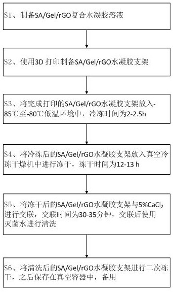
[0050] see Figure 1-9 As shown, a preparation method of a 3D printed hydrogel urethral stent includes the following steps:

[0051] S1, prepare SA / Gel / rGO composite hydrogel solution;

[0052] S2, using 3D printing to prepare SA / Gel / rGO hydrogel scaffolds;

[0053] S3, put the printed SA / Gel / rGO hydrogel scaffold in a low temperature environment of -85°C to -80°C, and the freezing time is 2-2.5h;

[0054] S4, put the frozen SA / Gel / rGO hydrogel scaffold into a vacuum freeze-drying machine for freeze-drying, and the freeze-drying time is 12-13 hours;

[0055] S5, lyophilized SA / Gel / rGO hydrogel scaffold with 5% CaCl 2 Carry out cross-linking, the cross-linking time is 30-35 minutes, and use sterilized water for cleaning after cross-linking;

[0056] S6, the washed SA / Gel / rGO hydrogel scaffold is lyophilized for a second time, and then stored in a vacuum container for later use.

[0057] Preparation of SA / Gel / rGO Composite Hydrogel

[0058] In step S1, the preparation of t...

Embodiment 2

[0079] On the basis of Example 1, the method further includes step: S7 , qualitatively analyzing the SA / Gel / rGO hydrogel scaffolds by means of a testing instrument.

[0080] In step S7, the testing instrument includes a Fourier transform infrared spectrometer, and Fourier transform infrared spectroscopy (FTIR) is used to characterize the functional groups of the SA / Gel / rGO composite hydrogel solution, and the prepared SA / Gel / rGO composite hydrogel is prepared. The gum solution was freeze-dried in a vacuum freeze dryer, after which it was finely ground with KBr (1:100) and compressed into flakes for infrared spectroscopy measurement in the range of 500-4000 cm -1 .

[0081] In step S7, the testing instrument further includes Raman spectroscopy, and qualitative analysis is performed on the incorporation of reduced graphene oxide in the SA / Gel / rGO composite hydrogel solution by Raman spectroscopy.

[0082] In step S7, the testing instrument further includes a scanning electron m...

Embodiment 3

[0093] On the basis of Example 2, the characterization of reduced graphene oxide (rGO) and the construction of composite hydrogels

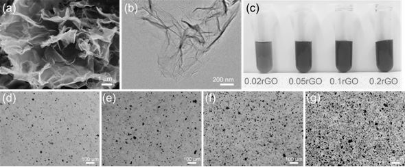
[0094] The monolayer rate of the reduced graphene oxide powder is increased by 80%, the diameter is 0.5-5 μm, and the thickness is 0.8-1.2 nm. Under SEM and TEM, rGO is a monolayer ( figure 2 a and b). Dispersion of rGO (1 mg mL -1 ) were diluted to concentrations of 0.02, 0.05, 0.1 and 0.2 mg mL -1 , they are all stable and uniform over several weeks, indicating that PVP can make the reduced graphene oxide well dispersed in water. As the concentration of reduced graphene oxide increases, the color of the solution changes from light to black, such as figure 2 c shown. To confirm the dispersion of reduced graphene oxide in the SA / Gel hydrogel composite solution, they were observed under an optical microscope. The results show that the reduced graphene oxide does not aggregate and is uniformly distributed (e.g. figure 2 d-g shown).

[00...


PUM

PropertyMeasurementUnit
Diameteraaaaaaaaaa
Thicknessaaaaaaaaaa

Abstract

The invention discloses a preparation method of a 3D printing hydrogel urethral stent. The preparation method comprises the following steps: S1, preparing an SA/Gel/rGO composite hydrogel solution; s2, preparing an SA/Gel/rGO hydrogel scaffold by using 3D printing; s3, putting the printed SA/Gel/rGO hydrogel stent into a low-temperature environment of-85 DEG C to-80 DEG C, and freezing for 2-2.5 hours; s4, putting the frozen SA/Gel/rGO hydrogel stent into a vacuum freeze-drying machine for freeze-drying, wherein the freeze-drying time is 12 to 13 hours; s5, the freeze-dried SA/Gel/rGO hydrogel scaffold and 5% CaCl2 are subjected to crosslinking, the crosslinking time is 30-35 minutes, and after crosslinking, the scaffold is washed with sterilized water; and S6, carrying out secondary freeze-drying on the cleaned SA/Gel/rGO hydrogel scaffold, and then storing in a vacuum container for later use. The SA/Gel/rGO nano-composite hydrogel is prepared by introducing an rGO solution into an SA/Gel mixed solution and is printed, so that the swelling property, the pore size and the tensile property of the hydrogel can be well improved.

Description

technical field [0001] The invention belongs to the technical field of 3D printing hydrogel urethral stents, and in particular relates to a preparation method of a 3D printing hydrogel urethral stent. Background technique [0002] Although biomimetic tissues and organs can be cultured in vitro, using traditional methods such as electrospinning, rapid prototyping, and freeze-drying, the fabricated biomimetic tissues cannot form three-dimensional structures compared to scaffolds. In addition, cells did not attach uniformly to the scaffold. Direct seeding of cells on the scaffolds may lead to cell death, further causing tissue or organ necrosis. 3D printing is an emerging technology that already has a wide range of applications in the field of tissue engineering. Compared with traditional manufacturing techniques, great progress has been made, but there are still problems such as low cell seeding efficiency, uneven distribution, and low spatial resolution. [0003] Due to th...

Claims


Application Information

Patent Timeline
IPC IPC(8): A61L27/44A61L27/52A61L27/54A61L27/56A61L27/58C08L5/04C08L89/00C08J3/075
CPCC08J3/075A61L27/443A61L27/52A61L27/56A61L27/54A61L27/58C08J2305/04C08J2389/00C08J2405/04C08J2489/00C08K3/042A61L2300/108A61L2300/404A61L2300/41A61L2300/604C08L5/04C08L89/00
Inventor 张楷乐李文尧王丽阳程婕杨熙陈剑锋傅强
Owner 张楷乐
Why Eureka
Try Eureka