Sewage total nitrogen removal device and operation method thereof

An operation method and nitrogen removal technology, applied in chemical instruments and methods, water/sewage multi-stage treatment, water/sludge/sewage treatment, etc., to achieve the effects of low effluent turbidity, convenient adjustment, and excellent energy consumption

Active Publication Date: 2022-07-12
GREENTECH ENVIRONMENTAL CO LTD
View PDF6 Cites 2 Cited by
  • Summary
  • Abstract
  • Description
  • Claims
  • Application Information

AI Technical Summary

Problems solved by technology

[0004] Based on the above characteristics of MABR and AGS, these two processes have the advantage of simultaneous nitrification-short-range denitrification-ANAMMOX reaction, but there is no related technology to take advantage of this feature to organically combine and design MABR and AGS Reasonable equipment and process flow to achieve low energy denitrification of sewage

Method used


Image

  • Sewage total nitrogen removal device and operation method thereof
  • Sewage total nitrogen removal device and operation method thereof

Examples


Embodiment 1

[0054] This embodiment provides a device for removing total nitrogen from sewage.

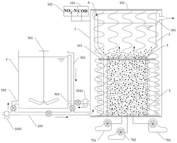
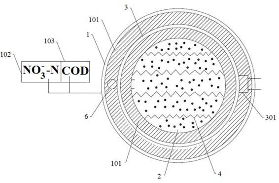
[0055] like figure 1 and figure 2 As shown, the sewage total nitrogen removal device includes a denitrification tank 1, a supplementary reaction zone 2, a sedimentation separation zone 3 and a standby anaerobic tank 5, wherein:

[0056] The precipitation separation zone 3 and the supplementary reaction zone 2 are located inside the denitrification tank 1, and the precipitation separation zone 3 is located above the supplementary reaction zone 2 and passes through a three-phase separator with the supplementary reaction zone 2 4 is connected, the upper part of the inner cavity of the sedimentation separation zone 3 is provided with an overflow weir 301, the overflow weir 301 protrudes from the side wall of the sedimentation separation zone 3, and the denitrified sewage flows through the overflow weir 301 to the denitrification zone 3. Outside nitrogen pool 1;

[0057] The outer wall of the se...

Embodiment 2

[0067] This embodiment provides a method for treating sewage by using the device provided in Embodiment 1.

[0068] (1) Turn on the inlet water pump 1041 and the main inlet valve, and the raw water enters the denitrification tank 1 for reaction. At this time, the primary aerator 701 and the tertiary aerator 703 are in operation, and the secondary aerator 702 is closed. state, the online COD detector 103 and the online nitrate detector 102 record the COD concentration and nitrate nitrogen concentration of the raw water of the denitrification tank 1 at a fixed frequency, and calculate the ratio of the COD concentration to the nitrate nitrogen concentration;

[0069] (2) The reacted raw water flows into the supplementary reaction zone 2 through the guide pipe 6 for supplementary reaction, and forms an upward flow by gravity flow;

[0070] (3) The upflow passes through the three-phase separator 4 to remove air bubbles and part of the aerobic granular sludge and then enters the pre...


PUM


Abstract

The invention relates to a sewage total nitrogen removal device and an operation method thereof, the sewage total nitrogen removal device comprises a denitrification tank, a precipitation separation zone and a supplementary reaction zone, the precipitation separation zone and the supplementary reaction zone are located in the denitrification tank, the precipitation separation zone is located above the supplementary reaction zone and is communicated with the supplementary reaction zone through a three-phase separator, and the three-phase separator is communicated with the three-phase separator. Sewage in the denitrification tank can flow into the supplementary reaction zone, and sewage subjected to denitrification treatment in the settling zone can directly flow out of the denitrification tank; the top surface of the precipitation separation area is sealed, the diameter of the top surface is larger than that of the bottom surface, and the supplementary reaction area is filled with aerobic granular sludge; an MABR membrane assembly is arranged in a space formed by the outer side walls of the precipitation separation area and the supplementary reaction area and the inner cavity of the denitrification tank, and an online COD detector and an online nitrate nitrogen detector are arranged on the side wall of the denitrification tank. The device provided by the invention is simple in operation, energy-saving and good in effluent quality.

Description

technical field [0001] The present disclosure relates to the technical field of sewage treatment, and in particular, to a sewage total nitrogen removal device and an operation method thereof. Background technique [0002] Membrane aeration bioreactor (MABR) is a new type of biomembrane combined process, in which the "membrane" is usually hollow fiber membrane, and its shape can be changed flexibly; the surface of the hollow fiber membrane is covered with biofilm, and the outside of the biofilm is a When treating the liquid phase composed of raw water, the surface of the hollow fiber membrane not only provides aeration but also serves as the carrier of the biofilm; in actual use, oxygen diffuses into the biofilm through the interface of the hollow fiber membrane / biofilm, making the biofilm from the inside out. An aerobic layer, a facultative anaerobic layer and an anaerobic layer are formed, and the pollutants in the raw water enter the biofilm in reverse through the biofilm / ...

Claims


Application Information

Patent Timeline
Patent Type & Authority Applications(China)
IPC IPC(8): C02F9/14C02F101/16
CPCC02F9/00C02F2209/08C02F2209/15C02F2001/007C02F1/20C02F2101/163C02F3/302Y02W10/10C02F3/208C02F3/2813C02F2209/38C02F2209/40C02F3/102C02F3/30C02F2101/16C02F2103/005C02F2203/006C02F2209/16
Inventor 刘牡段梦缘黎泽华孙凯苏英强朱希坤韩慧铭林晓峰李晋
Owner GREENTECH ENVIRONMENTAL CO LTD
Why Eureka
Try Eureka