Large-torque belt main shaft for numerical control grinding machine

A CNC grinding machine and high-torque technology, which is applied in the field of machine tools, can solve the problems of reduced inertial mass of machine tool spindles, difficulty in accurately tracking real-time thermal deformation, high initial investment and maintenance costs, etc., and achieves the effects of reducing thermal expansion rate, simple structure, and stable kinetic energy output

Active Publication Date: 2022-07-22
冈田精机(常州)有限公司
View PDF7 Cites 0 Cited by
  • Summary
  • Abstract
  • Description
  • Claims
  • Application Information

AI Technical Summary

Problems solved by technology

Traditional high-end precision CNC machine tools eliminate the influence of thermal errors. One is to embed the error compensation model into the CNC system, and passively accept the detection value sent by the sensor to perform error compensation. However, due to the nonlinear time-varying process of thermal deformation , the general model is difficult to accurately track real-time thermal deformation, the second is to build a constant temperature room, put the CNC machine tool in the constant temperature room and use a large air conditioner to actively adjust the temperature, but the initial investment and later operation and maintenance costs are extremely high
[0005] In view of this, the existing problems are studied and improved, and a high-torque belt spindle for CNC grinding machines is provided to solve the existing problems of torque weakening caused by the reduction of the inertial mass of the machine tool spindle and the influence of high temperature thermal expansion. , to achieve the purpose of solving problems and improving practical value

Method used


Image

  • Large-torque belt main shaft for numerical control grinding machine
  • Large-torque belt main shaft for numerical control grinding machine
  • Large-torque belt main shaft for numerical control grinding machine

Examples


Embodiment Construction

[0035] In order to make the objectives, technical solutions and advantages of the present invention clearer, the present invention will be further described in detail below with reference to the specific embodiments and the accompanying drawings. It should be noted that the embodiments of the present invention and the features in the embodiments may be combined with each other under the condition of no conflict.

[0036] It is understood that these descriptions are exemplary only and are not intended to limit the scope of the invention.

[0037] The following describes a high-torque belt spindle for a CNC grinding machine provided by some embodiments of the present invention with reference to the accompanying drawings.

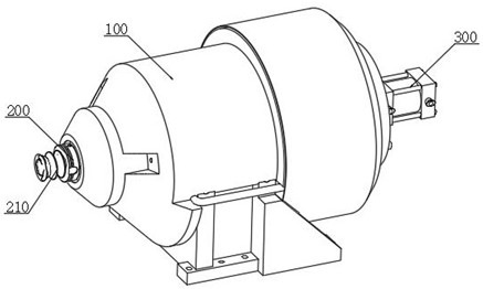
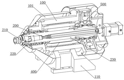
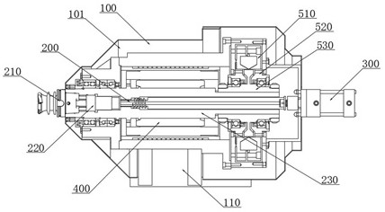
[0038] combine Figure 1-5 As shown, the present invention provides a high-torque belt spindle for a CNC grinding machine, including: an electric spindle box 100, a moving spindle 200, a control master cylinder 300, a built-in motor assembly 400 and a shaft s...


PUM


Abstract

The large-torque belt main shaft comprises an electric main shaft box, a moving main shaft, a control main cylinder, a built-in motor assembly and a shaft stabilizing assembly, a supporting seat is arranged on the bottom face of the electric main shaft box, and an air cooling cavity is formed in the inner side of the electric main shaft box; the control main cylinder is fixedly installed on one side of the electric spindle box, the output end of the control main cylinder is movably connected with one end of the moving spindle, and the moving spindle is rotationally connected to the inner side of the electric spindle box in a sleeved mode. In the invention, a built-in driving structure is adopted, and a rotor and stator structure is formed by a permanent magnet ring seat and a permanent magnet block which are sleeved outside a moving main shaft and an alternating current given by the surface of a magnet yoke stator; when the steel main shaft with large specific gravity accelerates and decelerates rapidly, the change of coil current on the surface of a magnet yoke stator is utilized to directly act on the main shaft to limit or increase the movement deflection force of the main shaft, and additional kinetic energy supplementation and kinetic energy collapse limitation are carried out in the acceleration and deceleration stages, so that stable kinetic energy output of the main shaft in the machining process is guaranteed.

Description

technical field [0001] The invention relates to the technical field of machine tools, in particular to a high-torque belt spindle for a numerically controlled grinding machine. Background technique [0002] In order to increase the cutting speed of a machine tool such as a machining center, it is desirable to rotate a spindle that fixes a tool and transmits a rotational force to the tool at a high speed. In order to realize the high-speed rotation of the main shaft, it is necessary to consider, for example, the lubrication and cooling of the bearing, and the dynamic balance of the rotating part including the main shaft; and it is also important to improve the static and dynamic rigidity of the main shaft, and to reduce its thermal deformation and inertial force. [0003] In the prior art, since there is no tool change signal sensing device when the spindle is changing the tool, the displacement of the tie rod is often not easy to control when the tool is broached and unloade...

Claims


Application Information

Patent Timeline
IPC IPC(8): B24B41/04B24B55/00B24B55/02
CPCB24B41/04B24B55/00B24B55/02
Inventor 陈亮曾燚刘涛吴明刚
Owner 冈田精机(常州)有限公司
Why Eureka
Try Eureka