Integrated cooling system for turbine casing and guide vane of aero-engine

A technology for aero-engines and turbine casings, applied in engine components, machines/engines, mechanical equipment, etc., can solve the problems of total pressure loss of mainstream gas, loss of air volume in external ducts, etc., and achieve the effect of increasing thrust

Pending Publication Date: 2022-07-22
BEIHANG UNIV
View PDF0 Cites 0 Cited by
  • Summary
  • Abstract
  • Description
  • Claims
  • Application Information

AI Technical Summary

Problems solved by technology

[0004] The cooling method usually used for the turbine casing is the air from the outer duct, in which a plurality of vent holes are opened on the guide vanes for the passage of air from the outer duct, and the air in the outer duct is impinged by the vent cooling. Cool the surface and interior of the turbine casing, and use the air in the outer duct, which may consume too much air in the outer duct, resulting in excessive total pressure loss of the mainstream gas

Method used


Image

  • Integrated cooling system for turbine casing and guide vane of aero-engine
  • Integrated cooling system for turbine casing and guide vane of aero-engine
  • Integrated cooling system for turbine casing and guide vane of aero-engine

Examples


Embodiment 1

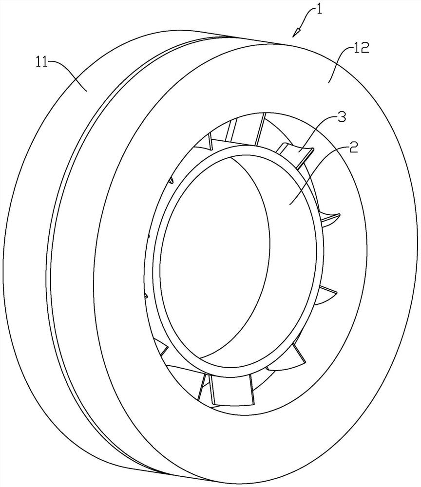
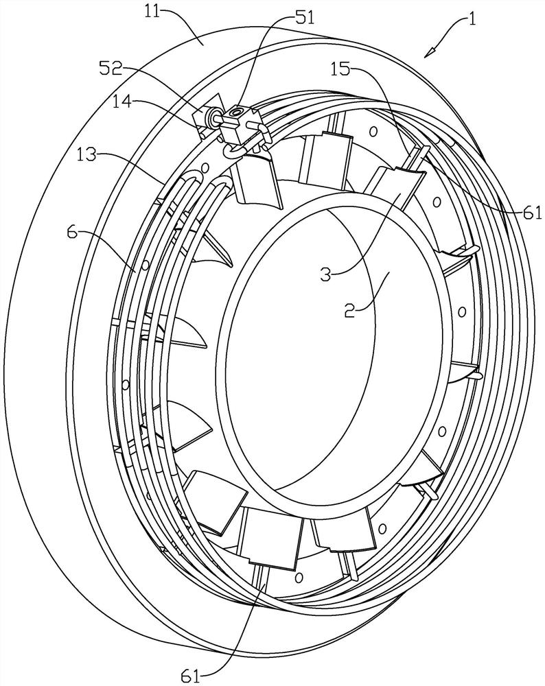
[0048] like figure 1 and figure 2 As shown, the integrated cooling system of the aero-engine turbine casing and guide vanes includes a heat exchanger 5, an electromagnetic pump 51, an expansion joint 52, and a cooling pipe 6; wherein the turbine casing 1 is provided with an annular cavity 13 and an installation cavity 14, and the installation cavity 14 and The annular cavity 13 communicates with each other, the cooling pipes 6 are installed on the inner side wall of the annular cavity 13 , and the cooling pipes 6 are periodically and uniformly distributed in the annular cavity 13 along the circumferential direction of the turbine casing 1 .

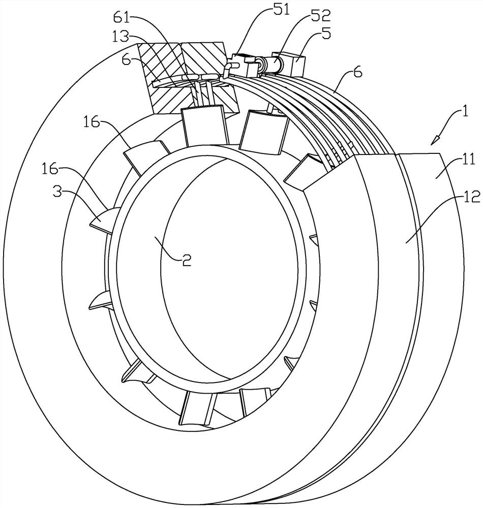
[0049] like figure 2 and image 3 As shown, the heat exchanger 5, the electromagnetic pump 51 and the expansion joint 52 are all installed on the inner side wall of the installation cavity 14, and the two connecting nozzles of the electromagnetic pump 51 are the liquid inlet nozzle and the liquid outlet nozzle respectively, wherein th...

Embodiment 2

[0061] like Image 6 As shown, the difference between the second embodiment of the present application and the first embodiment is only the guide vane 3. In the second embodiment of the present application, the accommodating cavity 4 in the guide vane 3 includes a plurality of cooling cavities 44 and a plurality of There are five cooling cavities 45. In the second embodiment of the present application, the preferred number of cooling cavities 444 is five, the preferred number of cooling cavities 45 is four, and the plurality of cooling cavities 44 are all located in the guide. On the side of the vane 3 away from the guide inner ring 2 , the plurality of cooling cavities 5 45 are all located on the side of the guide vane 3 close to the guide inner ring 2 .

[0062] The guide vane 3 is also provided with two connecting holes 46 . The two connecting holes 46 communicate with the two cooling chambers 44 44 in one-to-one correspondence, and correspond to the two vertical connecting...

Embodiment 3

[0066] like Figure 7As shown, the difference between the third embodiment of the present application and the first embodiment is only in the manner in which the guide vane 3 communicates with the cooling cavity 1 41 , the cooling cavity 2 42 and the cooling cavity 3 43 . In the third embodiment of the present application, The guide vane 3 is also provided with a plurality of circulation channels 4 34, one end of all the circulation channels 4 34 is communicated with the cooling cavity 2 42, and the other end of a part of the circulation channels 4 34 is communicated with the cooling cavity 1 41, The other end of the other part of the fourth circulation channel 34 is communicated with the third cooling cavity 43 .

[0067] The implementation principle of the third embodiment of the present application is as follows: in order to enhance the cooling effect of the cooling liquid after passing through the guide vanes 3 , the cooling liquid enters the cooling cavity 1 41 from the v...


PUM


Abstract

The invention discloses an aero-engine turbine casing and guide vane integrated cooling system, and belongs to the field of aero-engine turbine casing flow and heat exchange research. A guider inner ring and a plurality of guider vanes are mounted on a turbine casing; the cooling system comprises an electromagnetic pump, a heat exchanger, an expansion joint and a cooling pipeline; an annular cavity is formed in the turbine case, the cooling pipelines are installed on the inner wall of the annular cavity, the cooling pipelines are periodically and evenly distributed in the circumferential direction of the turbine case, and cooling liquid is contained in the cooling pipelines. A mounting cavity is further formed in the turbine case and communicates with the annular cavity; the electromagnetic pump, the expansion joint and the heat exchanger are all mounted in the mounting cavity, and one connecting pipe orifice of the electromagnetic pump is communicated with the cooling pipeline; one end of the expansion joint is communicated with the other connecting pipe orifice of the electromagnetic pump, the other end of the expansion joint is communicated with one connecting pipe orifice of the heat exchanger, and the other connecting pipe orifice of the heat exchanger is communicated with the cooling pipeline.

Description

technical field [0001] The present application relates to the research field of flow and heat exchange of aero-engine turbine casings, and in particular, to an integrated cooling system of aero-engine turbine casings and guide vanes. Background technique [0002] Increasing the gas temperature before the turbine is one of the key technologies to improve the thermal efficiency of the gas turbine. However, the excessively high gas temperature puts forward higher requirements on the performance of the hot end of the engine. [0003] Among them, the turbine casing is one of the main components that control the clearance of the turbine blade tip of the engine. The turbine casing bears the main thermal load, mechanical load and aerodynamic load, and the working environment is relatively harsh. As one of the hot-end components of the engine, when using a cooling medium to cool the turbine casing, it is necessary to ensure that the highest working temperature of the surface of the t...

Claims


Application Information

Patent Timeline
Patent Type & Authority Applications(China)
IPC IPC(8): F01D25/12F01D9/02
CPCF01D25/12F01D9/023Y02T50/60F01D25/08F01D25/14F01D9/065F01D5/185F01D5/181F05D2300/1618F05D2260/207F05D2260/205F05D2260/213F01D5/18F01D9/041F01D25/10F05D2220/323F05D2240/12
Inventor 罗翔张哲刘冬冬邬泽宇
Owner BEIHANG UNIV
Why Eureka
Try Eureka