Modularized photovoltaic direct current boost converter with low input current ripple, high gain and low loss

A technology of current ripple and DC boost, which is applied in the direction of converting DC power input to DC power output, adjusting electrical variables, and output power conversion devices, and can solve the problems of large volume, high cost, input current ripple and low cost of IIOS systems. Output gain optimization and other issues to achieve the effect of reducing the number of devices used, prolonging the service life and good application prospects

Pending Publication Date: 2022-07-22
NANJING UNIV OF AERONAUTICS & ASTRONAUTICS
View PDF0 Cites 1 Cited by
  • Summary
  • Abstract
  • Description
  • Claims
  • Application Information

AI Technical Summary

Problems solved by technology

[0005] The purpose of the present invention is to address the deficiencies of the above-mentioned background technology, to provide low input current ripple, high gain and low loss modularized photovoltaic DC boost converter, and for the IIOS converter composed of multiple photovoltaic sub-modules, adopt the buck-boost characteristic The current source dual active bridge converter is used as the boost unit of each photovoltaic sub-module, and the power equalization unit is connected in series between the output terminals of each photovoltaic sub-module. The phase shift angle realizes the independent MPPT control of each photovoltaic sub-module. By multiplexing the switching tubes in the secondary full bridge of each photovoltaic sub-module and controlling the phase shift angle between the secondary full bridges of adjacent sub-modules, the adjacent sub-modules are realized. Power transmission achieves the invention purpose of increasing the gain of the converter while reducing the turns ratio of the transformer winding and reducing the loss while reducing the input current ripple, and solves the problem that the existing IIOS system is large in size, high in cost and has no input current ripple and output Gain optimization technical issues

Method used


Image

  • Modularized photovoltaic direct current boost converter with low input current ripple, high gain and low loss
  • Modularized photovoltaic direct current boost converter with low input current ripple, high gain and low loss
  • Modularized photovoltaic direct current boost converter with low input current ripple, high gain and low loss

Examples


Embodiment Construction

[0031] The technical solutions of the invention will be described in detail below with reference to the accompanying drawings.

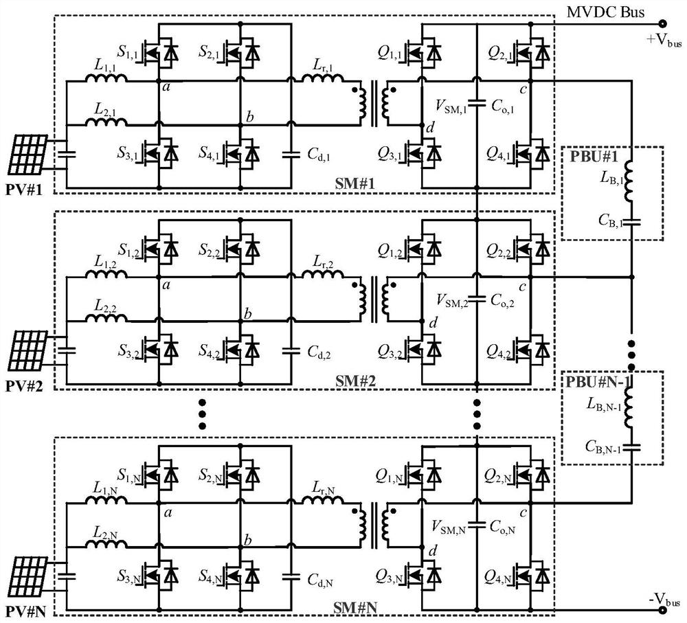
[0032] refer to figure 1 The invention discloses a new IIOS converter topology with low input ripple, high gain and low loss, which includes: N photovoltaic sub-modules SM#1~SM#N; N-1 power equalization units PBU#1~PBU# N-1 and the medium voltage DC bus MVDC Bus.

[0033] Each photovoltaic sub-module SM includes: a photovoltaic panel PV and an isolated DC-DC converter. The isolated DC-DC converter is a current source dual active bridge converter with buck-boost characteristics. The output of the photovoltaic panel The port is connected to the input port of the isolated DC-DC converter. The output port of the isolated DC-DC converter is the output port of the photovoltaic sub-module.

[0034] The primary side of the isolated DC-DC converter in each photovoltaic sub-module, that is, the input side, is an inverter circuit composed of two converters w...


PUM


Abstract

The invention discloses a low-input-current-ripple high-gain low-loss modular photovoltaic direct-current boost converter, and belongs to the technical field of power generation, power transformation or power distribution. The converter comprises N isolated photovoltaic sub-modules and N-1 LC power balancing units. The isolated photovoltaic sub-module comprises a photovoltaic cell panel and a current source type dual-active bridge converter with a buck-boost characteristic, the current source type dual-active bridge converter with the buck-boost characteristic is adopted to reduce input and output current ripples, the voltage gain is high, and the isolated photovoltaic sub-module is suitable for a wide voltage gain occasion. And the loss of the converter is greatly reduced due to relatively small current stress and soft switching working characteristics. The photovoltaic sub-modules reuse devices in secondary full-bridge circuits, independent MPPT control of the photovoltaic sub-modules is realized by controlling a phase shift angle between primary and secondary circuits, power transmission between adjacent sub-modules is realized by controlling a phase shift angle between secondary full bridges of the adjacent sub-modules, and power balance between the sub-modules is realized. The number of used switching devices is reduced, and cost is greatly reduced.

Description

technical field [0001] The invention relates to the technology of photovoltaic multi-port DC converters, in particular to a photovoltaic multi-port DC grid-connected system that prolongs the service life of photovoltaic panels under unbalanced output power of photovoltaic panels, and discloses a modular photovoltaic system with low input current ripple, high gain and low loss A DC boost converter belongs to the technical field of power generation, transformation or distribution. Background technique [0002] In the renewable energy power generation system, high-voltage direct current (HVDC, High-Voltage Direct Current) has the advantages of less loss, better stability, and no need for reactive power compensation, which is incomparable in large-capacity long-distance transmission and new energy power generation. The advantages and broad application prospects of the distributed photovoltaic power generation system have become one of the main ways of new energy power generation...

Claims


Application Information

Patent Timeline
Patent Type & Authority Applications(China)
IPC IPC(8): H02M3/335H02M1/14H02J3/38
CPCH02M3/33584H02M1/14H02J3/381H02J2300/26
Inventor 朱小全蒋黎明金科
Owner NANJING UNIV OF AERONAUTICS & ASTRONAUTICS
Why Eureka
Try Eureka