Sheet lamination combination laser welding method and device

A technology that combines laser and welding methods, applied in laser welding equipment, welding equipment, metal processing equipment, etc., can solve the problem of affecting the overall flatness of the product and the flatness of the contact surface, affecting the pressure-holding and sealing performance of the product, surface splashing and sticking, etc. problems, to achieve good appearance characteristics, avoid sticky damage, and reduce the effect of weld excess

Active Publication Date: 2022-07-29
SHANGHAI INST OF OPTICS & FINE MECHANICS CHINESE ACAD OF SCI
View PDF19 Cites 0 Cited by
  • Summary
  • Abstract
  • Description
  • Claims
  • Application Information

AI Technical Summary

Problems solved by technology

[0007] In order to solve two types of problems that affect the use of products in the laser welding of laminated laminated structures of thin plates: one is that the welding seams of aluminum alloy, stainless steel, galvanized sheet and other materials are prone to produce pores, cracks and other defects that affect the pressure-holding and sealing performance of the product; The second is that a large amount of weld heat accumulation causes product deformation, as well as weld instability and surface spatter and stickiness caused by welding fume and spatter, which affects the overall flatness of the product and the flatness of the contact surface

Method used


Image

  • Sheet lamination combination laser welding method and device
  • Sheet lamination combination laser welding method and device
  • Sheet lamination combination laser welding method and device

Examples


Embodiment 1

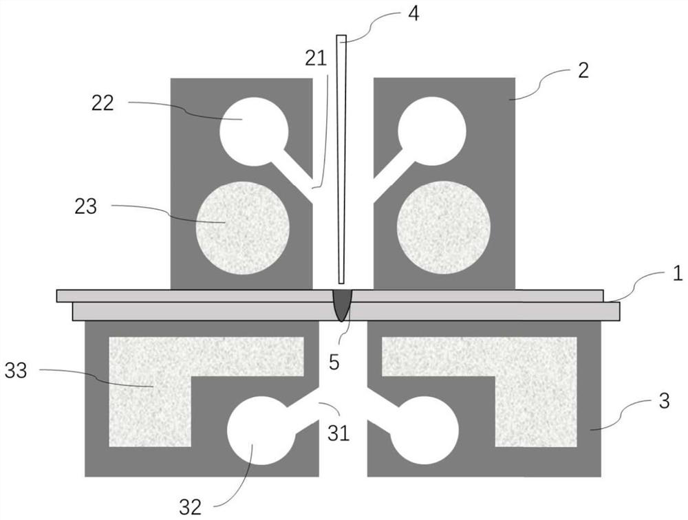
[0052] According to the position of the welding seam of the laminated composite product of thin plates, a pressing block 2 and a supporting block 3 are arranged in the clamping mechanism of the laser welding device, and the two layers of the laminated composite 1 are formed between the multi-layer boards through the mutual facing force between the two. In the areas to be welded, the contact force is applied by magnetic or mechanical force. like figure 1 As shown, an embodiment provided by the present invention is to set a blank area on the pressing block 2 , so that the laser beam 4 output by the laser welding system can act on the upper surface of the laminated combination through the blank area to generate the welding seam 5 . At the same time, small holes 21 are respectively provided on the two surfaces of the pressing block facing the area to be welded on the upper surface, and small hole connecting channels 22 are respectively provided inside the pressing block. Small ho...

Embodiment 2

[0054] like figure 1 As shown, on the basis that the pressing block and the supporting block are provided with small holes and connecting channels, cavities 23 are respectively set inside the blank area of ​​the pressing block 2 on both sides, and cavities 33 are respectively set on both sides of the supporting block 3; the pressing block The lowest point of the cavity 23 is not more than 5mm away from the upper surface of the stack assembly 1, preferably 2-3mm; the highest point of the support block cavity 33 is not more than 5mm away from the lower surface of the stack assembly 1, preferably 2- 3mm. The cross-sectional shape of the pressure block cavity 23 and the support block cavity 33 is preferably a circle or a rectangle or a combination thereof, and the pressure block cavity 23 and the support block cavity 33 are connected with an external cooling system, so that cooling The liquid circulates in the cavity. In one embodiment, the external cooling system is a circulati...

Embodiment 3

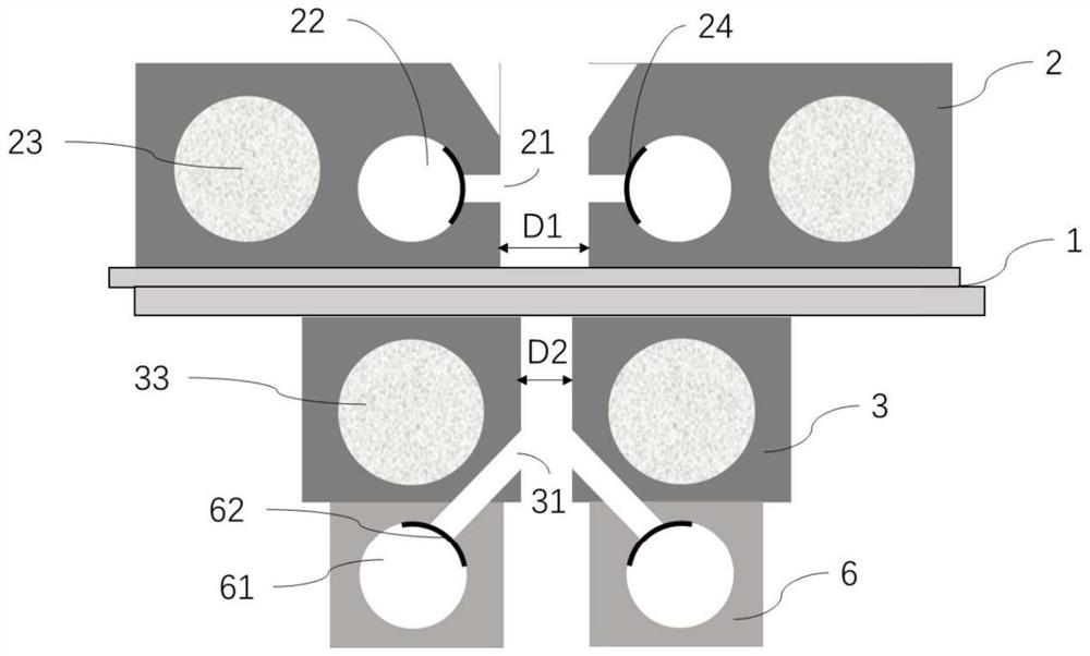
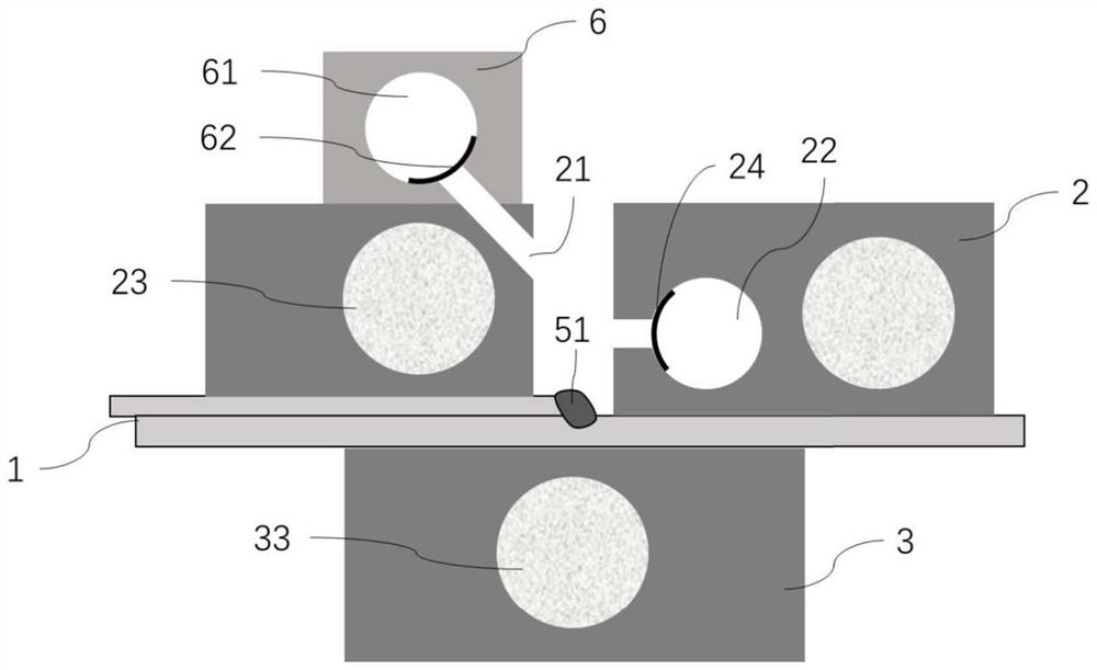
[0056] like figure 2 As shown, different structural forms of the pressure block and support block are used. In one embodiment, the blank area of ​​the pressure block has an interval D1 at the bottom and a larger distance at the upper part. The value of D1 is related to the width W1 of the weld on the upper surface. The value of satisfies W1≤D1≤W1+10 (unit mm), preferably W1≤D1≤3*W1. The blank area of ​​the support block has an interval D2, and the value of D2 and the value of the width W2 of the weld on the lower surface satisfy W2≤D2≤D1. In an embodiment, the weld does not penetrate the lower board, D2=W2=0, That is, there are no small holes and small hole channels in the support block. In another embodiment, a stopper 24 is set at the transition position between the connecting channel 22 of the pressure block and the small hole 21, and the back and forth translation or rotation of the stopper is controlled by program editing to close or open the small hole, and the stopper...


PUM


Abstract

The invention discloses a thin plate lamination combination laser welding method and device, and the method comprises the steps: enabling a laser beam to act on a welding area on the upper surface of a thin plate along a periodic repeated path, and forming a welding seam; and the thin plates are laminated and fixed, and smoke dust and splashing generated in the welding process are absorbed. The atmosphere environment in the welding seam forming process is controlled; and cooling and / or heating control is carried out on heat generated in the lamination and welding process of the thin plates. The welding process method which adopts a periodic repeated path and modulates laser energy is suitable for continuous sealing welding of a multi-layer sheet lamination combination, and has two characteristics of energy regulation and control to prevent a molten pool from being overheated and periodic scanning of laser beams to avoid small hole collapse; and control over the lamination combination temperature and welding fume is assisted, so that elimination of air holes and cracks of the welding seam is truly achieved, and the requirement for sealing and no leakage of the welding seam is met.

Description

technical field [0001] The invention relates to the field of thin-plate laminated composite welding, in particular to a thin-plate laminated composite laser welding method and device. Background technique [0002] In the body structure of the transportation industry, the appearance of sheet metal in the general equipment and construction industry, the cooling parts of thermal management systems in the energy and power industries, and other similar products, there are a large number of laminated composite structures of thin plates; Usually, it has the requirements of sealing and pressure keeping, and the commonly used materials are aluminum alloy, stainless steel, and galvanized steel plate. [0003] Existing laser welding technology usually cannot meet the requirements of surface quality and continuous welding seam without leakage, which makes it difficult to obtain large-scale application of laser welding technology, and cannot achieve the improvement of production efficien...

Claims


Application Information

Patent Timeline
Patent Type & Authority Applications(China)
IPC IPC(8): B23K26/21B23K26/14B23K26/082B23K26/70
CPCB23K26/21B23K26/14B23K26/082B23K26/703
Inventor 陶武杨上陆
Owner SHANGHAI INST OF OPTICS & FINE MECHANICS CHINESE ACAD OF SCI
Why Eureka
Try Eureka