
Ultrashort-cavity multi-wavelength single-frequency laser based on doping of different rare earth nanoparticles

A nanoparticle and ultra-short cavity technology, applied in the field of ultra-short cavity multi-wavelength single-frequency lasers, can solve the problems of complex laser structure, small interval between two wavelengths, and low output efficiency, and achieve strong selectivity, compact structure, low production cost

Pending Publication Date: 2022-07-29
SHANDONG UNIV
View PDF0 Cites 0 Cited by
  • Summary
  • Abstract
  • Description
  • Claims
  • Application Information

AI Technical Summary

Problems solved by technology

[0003] Two-color single-frequency light sources can usually be obtained in two ways. One is to combine two single-frequency lasers with different wavelengths. Combine laser beams, so the system is more complicated and the cost is higher
Another way is to use a dual-wavelength single-frequency fiber laser as a light source. There are also two implementation methods for a dual-wavelength single-frequency fiber laser. One is based on a gain fiber, but the two wavelengths generated by this scheme are relatively small. And it is necessary to suppress the competition of intracavity modes; the second is to use two kinds of gain fibers to achieve this. This solution usually adopts a double ring cavity structure and a structure in which two gain fibers are cascaded into the same linear cavity. The lasers of these structures usually need to insert more Therefore, the structure of this type of laser is complex, the output efficiency is low, and the stability is poor.

Method used


Image

  • Ultrashort-cavity multi-wavelength single-frequency laser based on doping of different rare earth nanoparticles
  • Ultrashort-cavity multi-wavelength single-frequency laser based on doping of different rare earth nanoparticles
  • Ultrashort-cavity multi-wavelength single-frequency laser based on doping of different rare earth nanoparticles

Examples


Embodiment 1

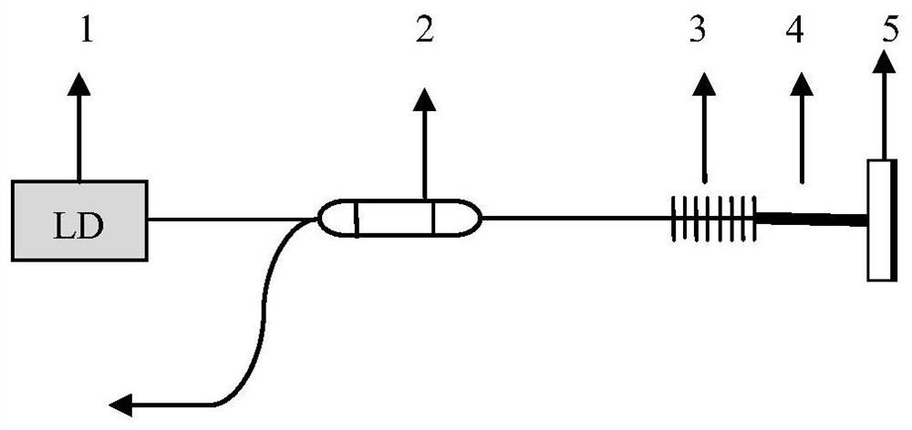
[0022] Example 1 The structure of the ultra-short cavity dual-wavelength single-frequency laser based on the doping of different rare earth nanoparticles provided in this example is as follows: figure 1 As shown, it includes a 976 nm pump source 1, a fiber wavelength division multiplexer 2, a Bragg grating group 3, a gain fiber 4 and a high-reflection mirror 5, which are arranged in sequence along the optical path.

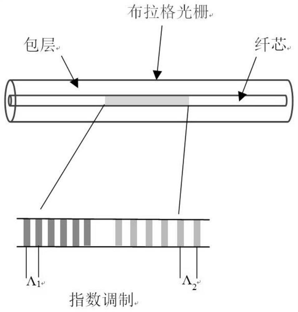
[0023] Among them, the pump source 1 is used to transmit the pump laser, the Bragg grating group 3 and the high reflection mirror form an ultra-short linear laser resonator, and a temperature control system is arranged outside the resonator to adjust and maintain the temperature of the laser resonator. The fiber wave The demultiplexer 2 connects the pump source 1 and the resonator, and injects the 976 nm pump laser emitted from the pump source into the resonator.

[0024] The pump source 1 described in this embodiment is a continuous pump source, and the center wa...

Embodiment 2

[0030] Example 2 The structure of the ultra-short cavity dual-wavelength single-frequency laser based on the doping of different rare earth nanoparticles provided in this example is as follows: figure 1 As shown, it includes a 976 nm pump source 1, a fiber wavelength division multiplexer 2, a Bragg grating group 3, a gain fiber 4 and a high-reflection mirror 5, which are arranged in sequence along the optical path.

[0031] Among them, the pump source 1 is used to transmit the pump laser, the Bragg grating group 3 and the high reflection mirror form an ultra-short linear laser resonator, and a temperature control system is arranged outside the resonator to adjust and maintain the temperature of the laser resonator. The fiber wave The demultiplexer 2 connects the pump source 1 and the resonator, and injects the 976 nm pump laser emitted from the pump source into the resonator.

[0032] The pump source 1 described in this embodiment is a pulsed pump source, and the center wavele...

Embodiment 3

[0038] Embodiment 3 The structure of the ultrashort cavity three-wavelength single-frequency laser based on different rare earth nanoparticles doping provided in this embodiment is as follows: figure 1 As shown, it includes a 976 nm pump source 1, a fiber wavelength division multiplexer 2, a Bragg grating group 3, a gain fiber 4 and a high-reflection mirror 5, which are arranged in sequence along the optical path.

[0039] Among them, the pump source 1 is used to transmit the pump laser, the Bragg grating group 3 and the high-reflection mirror form an ultra-short linear laser resonator, and a temperature control system is arranged outside the resonator to adjust and maintain the temperature of the laser resonator. The fiber wave The demultiplexer 2 connects the pump source 1 and the resonator, and injects the 976 nm pump laser emitted from the pump source into the resonator.

[0040] The pump source 1 described in this embodiment is a pulsed pump source, and the center wavelen...


PUM

PropertyMeasurementUnit
Lengthaaaaaaaaaa
Lengthaaaaaaaaaa
Gate lengthaaaaaaaaaa

Abstract

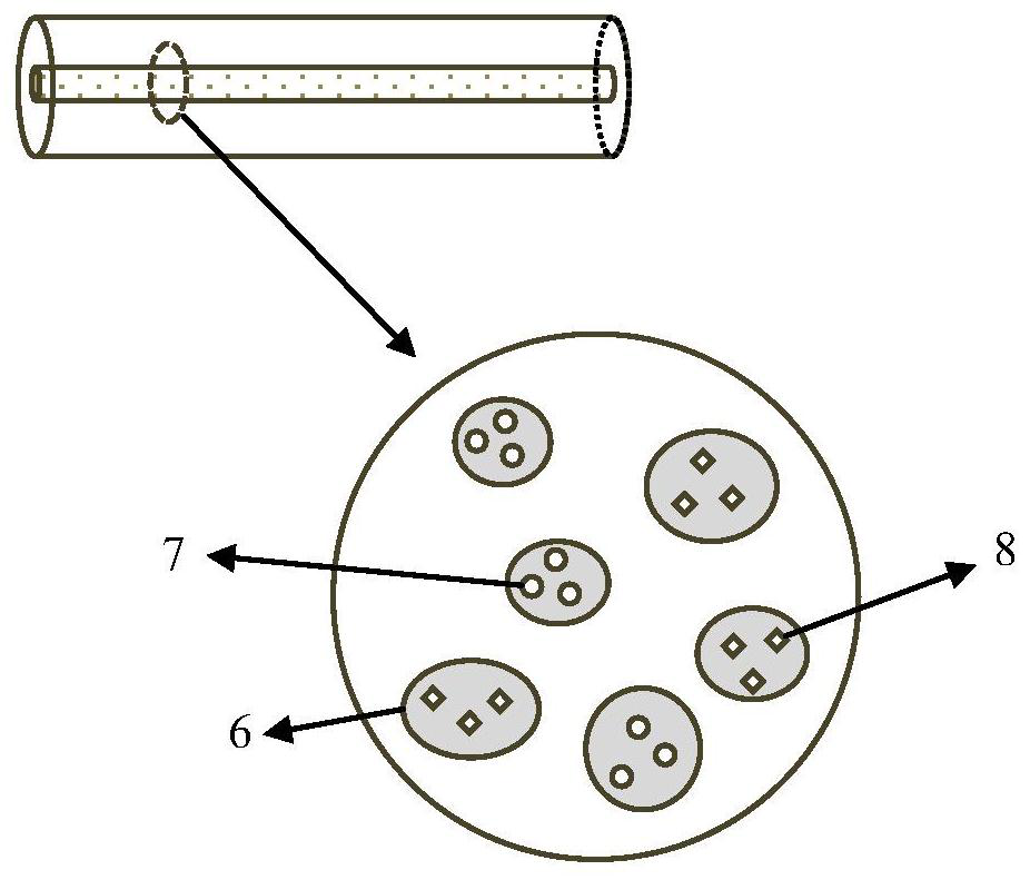
The invention belongs to the technical field of optical fiber lasers, and particularly relates to an ultra-short cavity multi-wavelength single-frequency laser based on doping of different rare earth nanoparticles. The ultra-short cavity multi-wavelength single-frequency laser based on different rare earth nanoparticle doping comprises a pumping source, an optical fiber wavelength division multiplexer, a Bragg grating group, a gain optical fiber and a high-reflectivity mirror which are sequentially arranged along an optical path, the Bragg grating group and the high-reflectivity mirror form an ultra-short linear laser resonant cavity; the gain fiber is located in the resonant cavity, one end of the gain fiber is connected with the grating region of the Bragg grating group, and the other end of the gain fiber is attached to the high-reflectivity mirror; the gain optical fiber is an optical fiber doped with more than two kinds of rare earth ions wrapped by nanoparticles. The ultra-short-cavity dual-wavelength laser is realized by utilizing the gain optical fiber doped with different rare earth nanoparticles, the structure of the ultra-short-cavity dual-wavelength laser is much more compact and stable than that of an existing dual-wavelength laser, the manufacturing cost is low, and the advantages of large output wavelength interval, good wavelength selectivity and the like can be realized.

Description

technical field [0001] The invention belongs to the technical field of fiber lasers, in particular to an ultra-short cavity multi-wavelength single-frequency laser doped based on different rare earth nanoparticles. Background technique [0002] Single-frequency fiber lasers have the advantages of narrow linewidth, low noise, and long coherence length. They have important applications in coherent optical communication, high-precision coherent ranging, coherent lidar, high-precision spectroscopy and gravitational wave detection. Especially in high-precision coherent ranging, the single-frequency laser has a very high measurement accuracy due to its extremely narrow linewidth. However, in some special application environments, such as in atmospheric detection, due to the uneven distribution and random fluctuations of atmospheric refractive index, certain measurement errors are often caused, thereby increasing the uncertainty of ranging. In order to reduce the error in the meas...

Claims


Application Information

Patent Timeline
IPC IPC(8): H01S3/067
CPCH01S3/06716H01S3/0675
Inventor 刘兆军赵微丛振华赵智刚谢永耀邵贤彬
Owner SHANDONG UNIV
Learn More