Automatic nutrient solution preparation device and method
A nutrient solution and liquid dispensing technology, applied in the field of medical devices, can solve the problems of difficulty in work, large manpower investment, danger, etc., and achieve the effects of maintaining dispersibility and stability, fast mixing of materials, and avoiding manual packaging.
- Summary
- Abstract
- Description
- Claims
- Application Information
AI Technical Summary
Problems solved by technology
Method used
Image
Examples
Embodiment 1
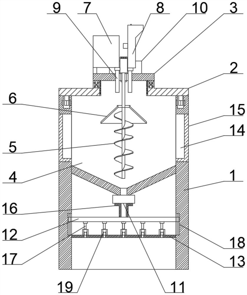
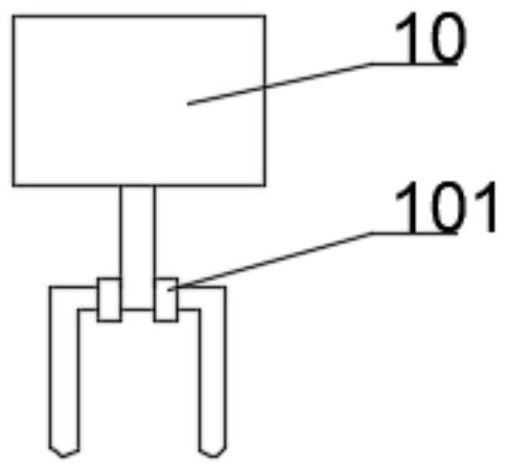
[0038] like figure 1 As shown, the automatic nutrient solution preparation device of this embodiment includes a device main body 1 with an opening at the upper end, a liquid dispensing chamber 4 arranged inside the device main body 1, and a liquid outlet pipe valve member 11 located at the lower end of the liquid dispensing chamber 4 (the present invention The pipe and valve parts include pipes and valves, and the valves can be electric, pneumatic and other valves in the prior art), and also include a ring cover 2 located at the opening position of the device body 1 (an exhaust valve is provided on the ring cover 2), movable The equipment cover 3 installed in the center of the ring cover 2 and the screw agitator 5 located in the liquid distribution chamber 4 are provided with an umbrella cover 6 above the blades of the screw agitator 5, and the upper end of the equipment cover 3 is provided with a liquid feeding mechanism 7 (similar to The structure of the water dispenser in the...
Embodiment 2
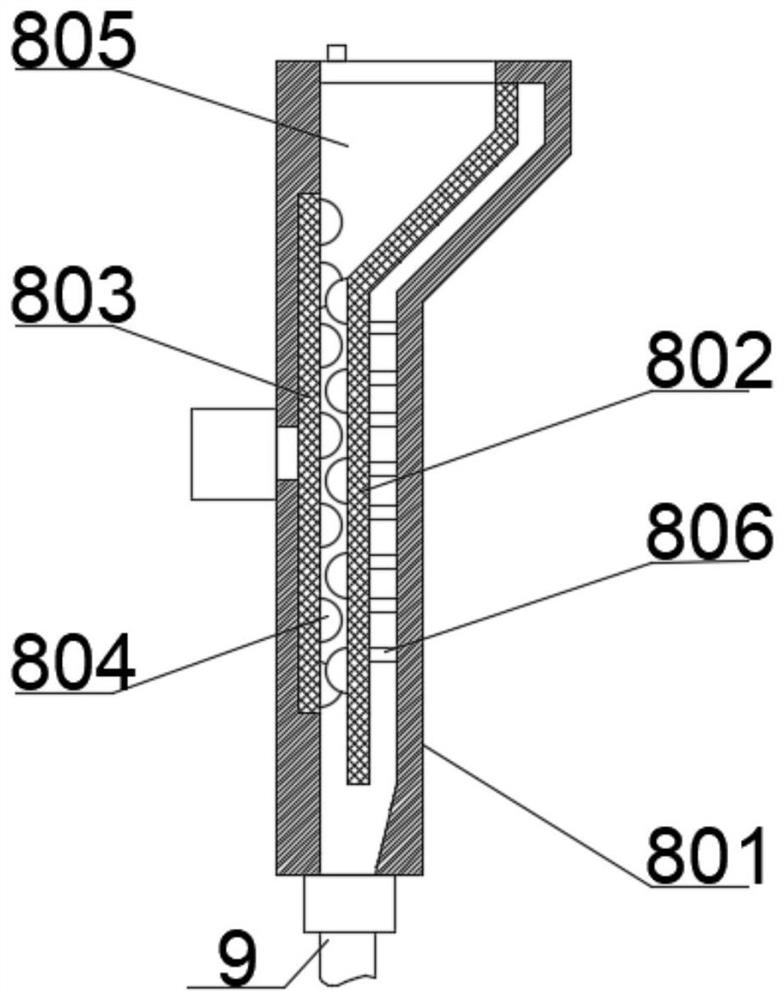
[0044] like figure 2 As shown, on the basis of Embodiment 1, the fixed feed assembly 8 includes a housing 801, a movable plate 802 and a rotating plate 803 located on both sides of the inner casing 801 (the rotating plate 803 is driven by a motor outside the casing 801), and the movable plate The channel 805 between the movable plate 802 and the rotating plate 803 and the elastic member 806 (preferably a spring) located between the movable plate 802 and the inner wall of the housing 801, the movable plate 802 and the rotating plate 803 are distributed on the opposite surfaces of the several rolling balls 804. When the rotating plate 803 rotates, the moving plate 802 and the rotating plate 803 reciprocate between the overlapping and separating states. After the large particles enter the channel 805, the rotating plate 803 and the moving plate 802 sometimes contact and overlap when the rotating plate 803 rotates. Separation, the large particles are milled by the rolling balls 8...
Embodiment 3
[0046] like Figure 4 As shown, on the basis of Embodiments 1 and 2, a first vibration damping mechanism is provided between the protrusion at the lower end of the ring cover 2 and the groove of the opening of the device body 1, and the first vibration reduction mechanism includes a protrusion located at the lower end of the ring cover 2. The first electromagnet 20 and the first magnets 21 located on both sides of the inner wall of the groove at the opening of the device body 1, the magnetic poles of the first electromagnet 20 are opposite to the magnetic poles of the first magnets 21 on both sides respectively. The magnetic poles and the first magnets 21 on both sides are located on the same line. Since the vertical direction of the ring cover 2 bears the gravity of the equipment cover 3 and various equipments, the main vibration is generated in the horizontal direction. The magnetic poles of a magnet 21 are opposite, which can limit the movement of the ring cover 2 in the ho...
PUM
 Abstract
Description
Claims
Application Information
 - R&D
- Intellectual Property
- Life Sciences
- Materials
- Tech Scout
- Unparalleled Data Quality
- Higher Quality Content
- 60% Fewer Hallucinations
Browse by: Latest US Patents, China's latest patents, Technical Efficacy Thesaurus, Application Domain, Technology Topic, Popular Technical Reports.
© 2025 PatSnap. All rights reserved.Legal|Privacy policy|Modern Slavery Act Transparency Statement|Sitemap|About US| Contact US: help@patsnap.com


