
Method and apparatus for non-destructive lithographic patterning of quantum dots

A technology of lithographic patterns and quantum dots, which is applied in the direction of photomechanical equipment, optics, pattern surface photolithography, etc., can solve the problems of reducing the luminous properties of quantum dots, and achieve the performance of LED devices, mild reaction conditions, and maintenance The effect of optical properties

Pending Publication Date: 2022-08-02
TSINGHUA UNIV
View PDF1 Cites 0 Cited by
  • Summary
  • Abstract
  • Description
  • Claims
  • Application Information

AI Technical Summary

Problems solved by technology

[0003] The existing schemes that can realize the patterning of quantum dots generally use traditional photoresist, but the introduction of photoresist will reduce the luminescent properties of quantum dots themselves, so a new and non-destructive quantum dot patterning method is urgently needed

Method used


Image

  • Method and apparatus for non-destructive lithographic patterning of quantum dots
  • Method and apparatus for non-destructive lithographic patterning of quantum dots
  • Method and apparatus for non-destructive lithographic patterning of quantum dots

Examples


Embodiment 1

[0059] Example 1: Patterning at 254nm

[0060] According to the patterning process, the light source is selected as 254nm ultraviolet light, preferably the illumination dose is greater than 10mJ / cm 2 The specific patterning process is as follows: in the air, spin-coating a mixed solution of quantum dots (20 mg / mL) and M570 (1 mg / mL) in toluene for 30 seconds at 2000 rpm, and then use 200 mJ under UV light at 254 nm. / cm 2 Dose exposure, elution and development through toluene solution, to obtain such as Figure 4 Fluorescence micrographs of red-green-blue are shown.

Embodiment 2

[0061] Example 2: Patterning at 254 nm

[0062] According to the patterning process, in the glove box, under the condition of inert gas atmosphere, the light source is selected to be 254nm ultraviolet light, and the preferred light dose is greater than 10mJ / cm 2 . The specific patterning process is as follows: in a glove box, under an inert gas atmosphere, spin-coating a mixed solution of quantum dots (20 mg / mL) and M570 (1 mg / mL) in toluene at 2000 rpm for 30 seconds, and then at 254 nm 200mJ / cm under UV light 2 Dose exposure, elution and development through toluene solution, to obtain such as Figure 5 Fluorescence micrographs of red-green-blue are shown.

Embodiment 3

[0063] Example 3: 365nm patterning results

[0064] According to the patterning process, in the glove box, under the condition of inert gas atmosphere, the selected light source is 365nm ultraviolet light, and the preferred light dose is greater than 10mJ / cm 2 . The specific patterning process is as follows: in a glove box, under nitrogen atmosphere: spin coating a mixed solution of quantum dots (20 mg / mL) and M570 (1 mg / mL) in toluene at 2000 rpm for 30 seconds, and then at 365 nm 200mJ / cm under UV light 2 Dose exposure, elution and development through toluene solution, to obtain such as Image 6 Fluorescence micrographs of red-green-blue are shown.


PUM


Abstract

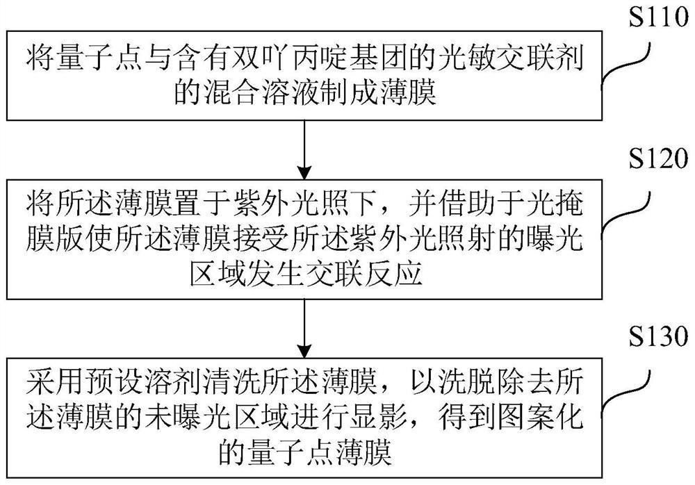
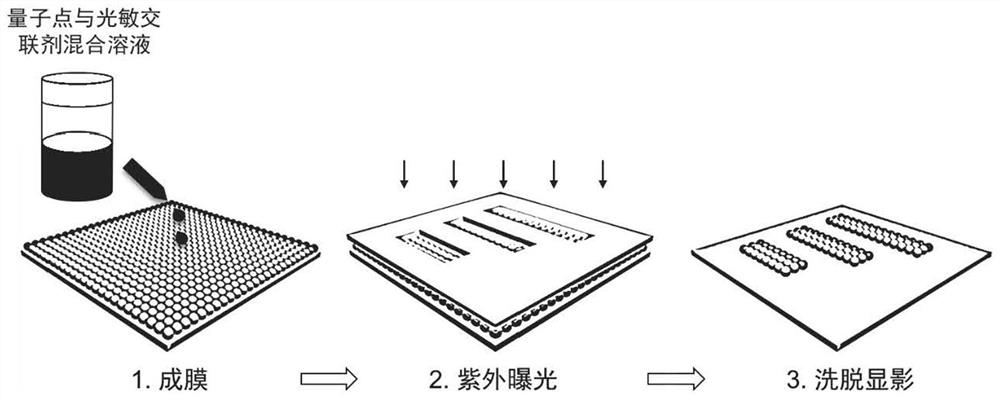
The invention provides a lossless photoetching patterning method and equipment for quantum dots. The method comprises the following steps: preparing a thin film from a mixed solution of the quantum dots and a photosensitive cross-linking agent containing a diaziridine group; placing the film under the irradiation of ultraviolet light, and enabling the exposure area of the film, which is irradiated by the ultraviolet light, to be subjected to a cross-linking reaction by means of a photomask; and cleaning the thin film by adopting a preset solvent to elute and remove an unexposed region of the thin film for developing to obtain the patterned quantum dot thin film. According to the method, surface ligands of the quantum dots are cross-linked through photolysis reaction of the photosensitive cross-linking agent, introduction of complex photoresist is avoided, quantum dot photoinduced patterning is achieved, and the method can be compatible with photoetching machine systems which are widely applied at present and have different ultraviolet wavelengths and is easy to popularize and implement.

Description

Technical field [0001] The present invention relates to the field of display, and more specifically, to a method and equipment for lossless photolithography patterning of quantum dots. Background technique [0002] Based on the quantum confinement effect, quantum dots have excellent luminescent properties such as broadband absorption, narrow-band emission, and continuously adjustable peak positions. At the same time, quantum dots are solution processable, which avoids the use of expensive vacuum equipment, making the large-scale mass production of quantum dots in fields such as display lighting, solar cells, and photoelectric detection practical. Patterning of quantum dots is to pixelate solution quantum dots, which is the only way to turn quantum dots into formed optoelectronic devices and even into commercial products. [0003] Existing solutions that can pattern quantum dots generally use traditional photoresist. However, the introduction of photoresist will reduce the l...

Claims


Application Information

Patent Timeline
Patent Type & Authority Applications(China)
IPC IPC(8): G03F7/00
CPCG03F7/0005
Inventor 张昊李景虹卢少勇
Owner TSINGHUA UNIV
Learn More