Method and apparatus for manufacturing a color conversion filter

a technology of color conversion filter and manufacturing method, which is applied in the direction of photosensitive materials, identification means, instruments, etc., can solve the problems of pattern shape reproducibility and pattern deformation in subsequent manufacturing steps, reduce efficiency, and reduce the efficiency of filtering, so as to reduce the deformation or the like of the color conversion layer, shorten the process, and simple mechanisms

Active Publication Date: 2008-06-03
SHARP KK
View PDF10 Cites 3 Cited by
  • Summary
  • Abstract
  • Description
  • Claims
  • Application Information

AI Technical Summary

Benefits of technology

[0007]An object of the invention therefore is to provide a method of manufacturing a color conversion filter that can simplify a manufacturing process and enables high-resolution patterning, as well as to provide an apparatus to be used to perform such a method.
[0017]The above-constituted manufacturing methods according to the invention make it possible to form high-resolution color conversion layers by self-alignment using the color filter layers as a mask. Since radicals are generated by causing the optical radical generating agent contained in the coloring matter layer to react with auxiliary ultraviolet light, color conversion layers can be formed at high speed. Further, the invention eliminates the need for forming patterns of color conversion layers by photolithography, which makes it possible to shorten the process. Further, since thicker color conversion layers can be formed so as to be integral with a planarized layer, deformation or the like of the color conversion layers can be suppressed even if their width is small relative to the film thickness. Therefore, the methods of the invention make it possible to manufacture color conversion filters that are used for micro-display devices (e.g., viewfinders of video cameras). Still further, since alignment need not be performed in the exposure for formation of color conversion layers, the color conversion layer forming apparatus and the color conversion filter manufacturing apparatus according to the invention have simple mechanisms.

Problems solved by technology

In addition to realization of a high-resolution color display function and long-term stability of characteristics including the color reproducibility, provision of color conversion filters having high color conversion efficiency is an important issue for the practical use of color display devices.
However, if the density of a color conversion coloring material is made higher in order to increase the color conversion efficiency, problems occur such as reduced efficiency due to what is called density extinction and decomposition with age of the color conversion coloring matter.
However, if patterning should be performed in such a manner that the width of each pattern is smaller than the film thickness, issues such as pattern shape reproducibility and pattern deformation arise in subsequent manufacturing steps.
For example, to manufacture a full-color display device which has at least red, green, and blue color conversion layers, a complicated manufacturing process consisting of a large number of steps is required.

Method used


Image

  • Method and apparatus for manufacturing a color conversion filter
  • Method and apparatus for manufacturing a color conversion filter
  • Method and apparatus for manufacturing a color conversion filter

Examples


example 1

[0096]After a blue filter material (Color Mosaic CB-7001 of Fujifilm Arch Co., Ltd.) was applied to a transparent glass substrate 1 by spin coating, patterning was performed by photolithography. As a result, a blue color filter layer 2B was formed in line patterns, wherein the lines were 0.1 mm in width, and 2 μm in thickness, separated by 0.33 mm and extended in the vertical direction.

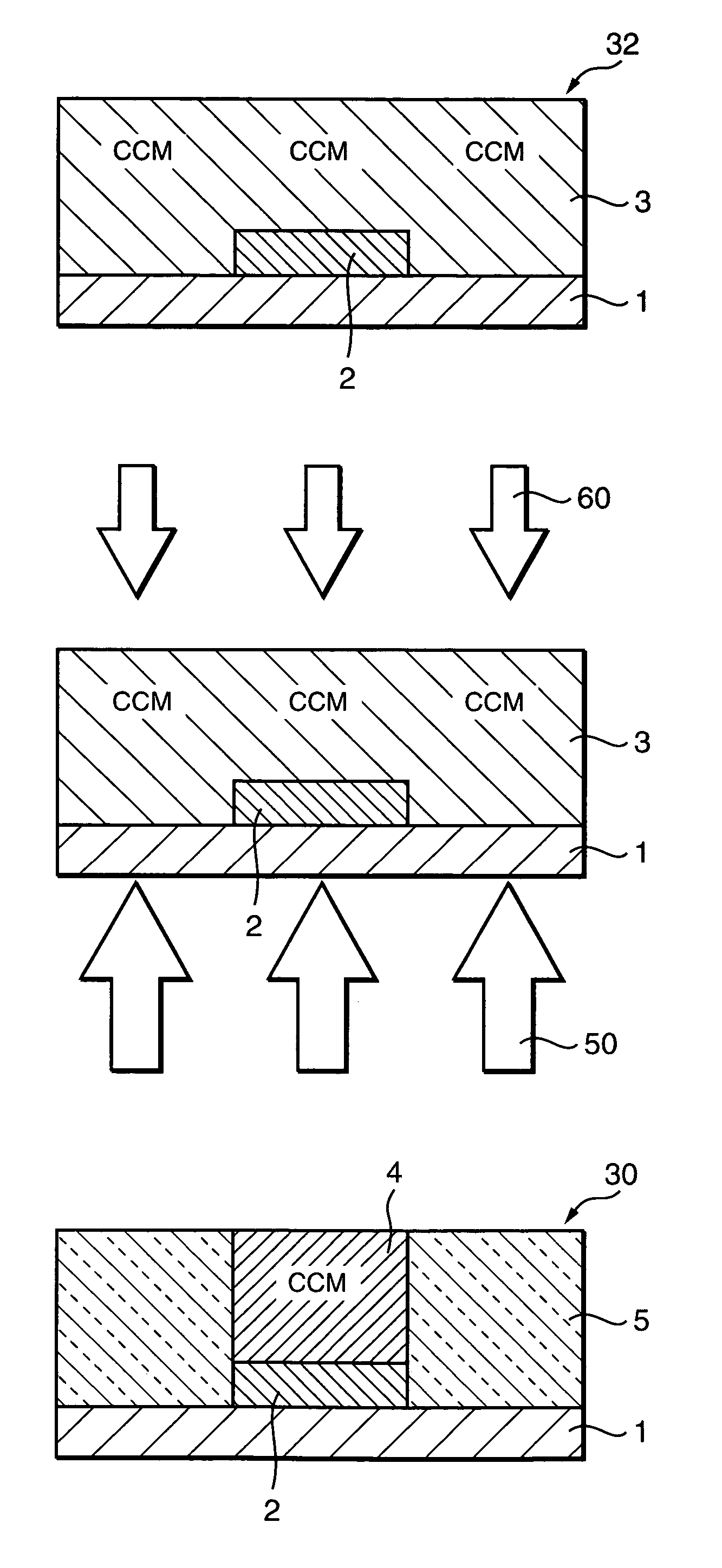
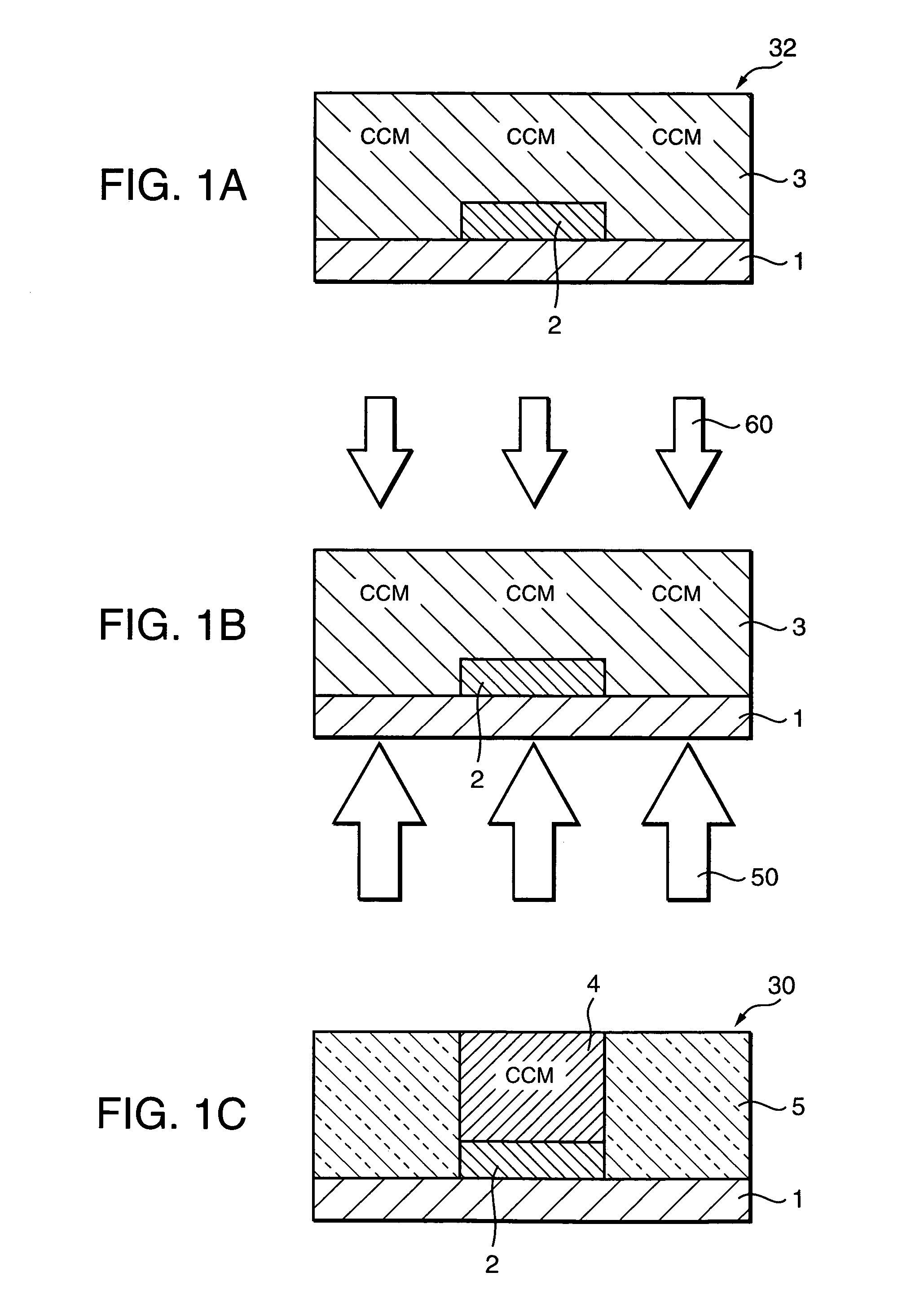
[0097]Then, a solution of fluorescent light conversion coloring matter was prepared in which rhodamine 6G (0.3 part by weight), Basic Violet 11 (0.3 part by weight), and coumarin 6 (0.3 part by weight) were dissolved in a propylene glycol monoethyl acetate solvent (120 parts by weight). PMMA (poly(methyl methacrylate); 100 parts by weight) and di-tert-butyl peroxide (1 part by weight) were added to and dissolved in the prepared solution. As a result, a coating liquid was obtained. The coating liquid was applied by spin coating and dried by heating, whereby a 7-μm-thick coloring matter layer 3 was form...

example 2

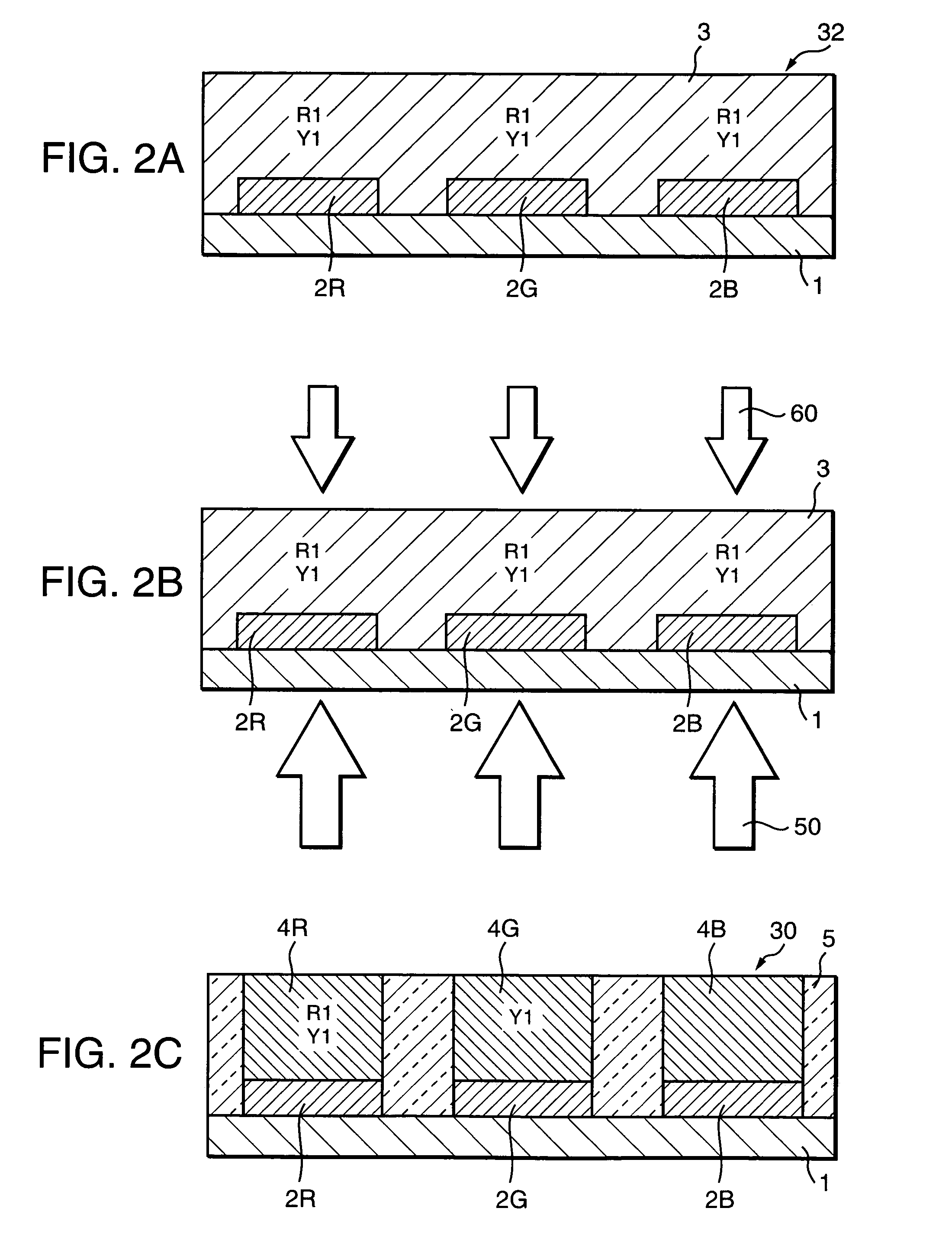
[0101]After a blue filter material (Color Mosaic CB-7001 of Fujifilm Arch Co., Ltd.) was applied to a transparent glass substrate 1 by spin coating, patterning was performed by photolithography. As a result a blue color filter layer 2B was formed in line patterns, the lines being 0.1 mm in width, separated by 0.33 mm, and 2 μm in thickness, and extended in the vertical direction.

[0102]After a green filter material (Color Mosaic CG-7001 of Fujifilm Arch Co., Ltd.) was applied, by spin coating, to the substrate 1 on which the blue color filter layer 2B was formed, patterning was performed by photolithography. As a result, a green color filter layer 2G was formed in line patterns, the lines being 0.1 mm in width, separated by 0.33 mm, and 2 μm in thickness, and extended in the vertical direction.

[0103]Then, after a red filter material (Color Mosaic CR-7001 of Fujifilm Arch Co., Ltd.) was applied by spin coating, patterning was performed by photolithography. As a result, a red color fil...

example 3

[0107]After a black mask material (Color Mosaic CK-7000 of Fujifilm Arch Co., Ltd.) was applied to a transparent substrate 1 by spin coating, patterning was performed by photolithography, whereby a 1.5-μm-thick black mask 6 having a plurality of openings each measuring 0.33 mm (vertical)×0.09 mm (horizontal) were obtained. The interval between the openings were set at 0.03 mm in both of the vertical and horizontal directions.

[0108]Then, after a blue filter material (Color Mosaic CB-7001 of Fujifilm Arch Co., Ltd.) was applied by spin coating, patterning was performed by photolithography. As a result, a blue color filter layer 2B was formed in line patterns, the lines being 0.1 mm in width, separated by 0.33 mm, and 2 μm in thickness, and extended in the vertical direction.

[0109]After a green filter material (Color Mosaic CG-7001 of Fujifilm Arch Co., Ltd.) was applied, by spin coating, to the substrate 1 on which the blue color filter layer 2B was formed, patterning was performed by...


PUM

PropertyMeasurementUnit
wavelengthaaaaaaaaaa
sublimation temperatureaaaaaaaaaa
temperatureaaaaaaaaaa

Abstract

A method and apparatus for manufacturing a color conversion filter. The method includes forming a color filter layer on a transparent substrate. A coloring matter layer containing color conversion coloring matter and an optical radical generating agent are formed on the substrate and the filter layer. The coloring matter layer is exposed to coloring matter decomposition light applied through the substrate and the filter layer. The coloring matter layer also is exposed to auxiliary ultraviolet light applied from the side of the coloring matter layer. This forms a color conversion layer at a position corresponding to the filter layer. The optical radical generating agent is heat vaporized. The color conversion coloring matter is decomposed by light whose wavelength is outside a range that the color filter layer transmits. The coloring matter decomposition light includes a wavelength component that decomposes the color conversion coloring matter. The color conversion layer emits, through wavelength profile conversion, light that the color filter layer transmits.

Description

BACKGROUND OF THE INVENTION[0001]1. Field of the Invention[0002]The invention relates to a method of manufacturing, and apparatus for use in manufacturing a color conversion filter that enables multicolor display. The color conversion filter can be used, for example, for the display provided by image sensors, personal computers, word processors, TV receivers, facsimile machines, audio apparatus, video apparatus, car navigation apparatus, desktop calculators, telephones, portable terminals, industrial measuring instruments, and related devices.[0003]2. Background Art[0004]In recent years, as one method for realizing multicolor or full-color display devices, a color conversion method has been studied that employs, as filters, color conversion coloring matter (or material) that absorbs near ultraviolet light, blue light, bluish green light, or white light and emits light in visible ranges through wavelength profile conversion. See, for example, Japanese Patent Publications JP-A-8-27939...

Claims


Application Information

Patent Timeline
Patent Type & Authority Patents(United States)
IPC IPC(8): G02F1/23G09F9/30G02B5/20G02F1/1335G09F9/00H01L27/32H01L51/50H01L51/52H05B33/10H05B33/12
CPCG02B5/201G02F1/133514H01L27/322H01L51/5237H01L2251/5315H10K59/38H10K2102/3026H10K59/872G02B5/20G02F1/23H05B33/12H10K50/841
Inventor KAWAGUCHI, KOJIKOBAYASHISAKURAI, KENYA
Owner SHARP KK
Why Eureka
Try Eureka