Combustible gas micro-leakage detection device and method based on quantum cascade laser

A leak detection device, quantum cascade technology, applied to the measurement device, by detecting the appearance of fluid at the leak point, the direction of the instrument, etc., can solve the problems of being easily interfered by other gases, high lower limit of the alarm, low sensitivity, etc., to achieve output High power, low maintenance cost, high selectivity effect

Pending Publication Date: 2022-08-05
HENAN HANWEI ELECTRONICS
View PDF0 Cites 0 Cited by
  • Summary
  • Abstract
  • Description
  • Claims
  • Application Information

AI Technical Summary

Problems solved by technology

[0005] Aiming at the technical problems of traditional through-beam combustible gas a

Method used


Image

  • Combustible gas micro-leakage detection device and method based on quantum cascade laser
  • Combustible gas micro-leakage detection device and method based on quantum cascade laser

Examples


Example Embodiment

[0025] Example 1

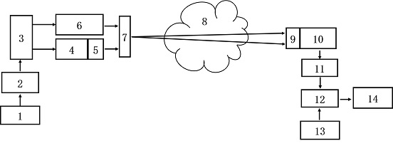
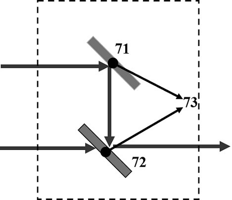
[0026] like figure 1 As shown, a combustible gas micro-leakage detection device based on a quantum cascade laser includes a transmitting end and a receiving end, the transmitting end corresponds to the receiving end, and the transmitting end includes a quantum cascade laser 4 and a visible light laser 6, and the quantum level The combined laser 4 is used for emitting infrared laser light, and the visible light laser 6 is used for emitting visible light. The wavelength band of visible light is 390-770 nm, which is used to indicate the optical path of invisible light, which is convenient for equipment installation and daily maintenance. Both the quantum cascade laser 4 and the visible light laser 6 are driven to emit light by the first control circuit 3 controlled by the first MCU2. Both the quantum cascade laser 4 and the visible light laser 6 are connected with the optical path coupling shaping unit 7, and the optical path coupling shaping unit 7 is arrange...

Example Embodiment

[0039] Example 2

[0040] A method for detecting micro-leakage of combustible gas based on a quantum cascade laser, the infrared laser emitted by the quantum cascade laser 4 and the visible light emitted by the visible light laser 6 enter the optical path coupling and shaping unit 7 for coupling and shaping, and are coupled into a beam of coaxial light to emit , the target gas 8 in the monitoring area absorbs the infrared light in the coaxial light, the photodetector 10 receives the light signal passing through the target gas and converts it into an electrical signal, and transmits it to the signal processing circuit 11, which amplifies and converts the electrical signal Demodulate to get the first harmonic signal 1 f and the second harmonic signal 2 f , the second MCU 12 calculates the concentration of the target gas 8 by fitting the two harmonic signals, and issues an alarm when the obtained concentration reaches a preset threshold.

[0041] The method for calculating the ...


PUM


Abstract

The invention provides a combustible gas micro-leakage detection device and a combustible gas micro-leakage detection method based on a quantum cascade laser, which are used for solving the problems that the traditional combustible gas detection device is high in detection lower limit, low in sensitivity and susceptible to cross interference of other gas components. The device comprises a transmitting end and a receiving end, the transmitting end corresponds to the receiving end, the transmitting end comprises a quantum cascade laser and a visible light laser, a first MCU drives the quantum cascade laser and the visible light laser to emit laser through a first control circuit, and the quantum cascade laser and the visible light laser are both connected with a light path coupling shaping unit; the receiving end comprises a photoelectric detector, the photoelectric detector is arranged on the light path of the light path coupling and shaping unit emitting infrared rays, and the photoelectric detector is connected with the second MCU through a second control circuit. According to the invention, trace leakage of combustible gas can be detected, the detection sensitivity is high, a fingerprint absorption peak of target gas is selected as a detection wavelength, and cross interference of other gas components is avoided.

Description

technical field [0001] The invention relates to the technical field of infrared laser gas detection, in particular to a device and method for detecting micro-leakage of combustible gas based on a quantum cascade laser. Background technique [0002] Combustible gas alarms are widely used in metallurgy, gas, chemical, petroleum and other industries to detect the leakage of combustible gas in indoor and outdoor dangerous places. It is an indispensable instrument to ensure personal safety and production safety. Among them, the through-beam combustible gas alarm is a detection instrument suitable for a large area of ​​open space. It is widely used in oil pipeline systems, large oil depots, petroleum liquefied gas stations, oil production platforms and other places prone to combustible gas leakage. [0003] Traditional through-beam combustible gas alarms use xenon lamps or near-infrared semiconductor lasers as light sources. Although they have certain advantages in system cost, th...

Claims


Application Information

Patent Timeline
IPC IPC(8): G01M3/04G01N21/3504
CPCG01M3/04G01N21/3504
Inventor 陈海永孟庆逍武传伟杨清永王海超米洛锋冉顺杰
Owner HENAN HANWEI ELECTRONICS
Why Eureka
Try Eureka