Device and method suitable for comprehensive treatment of post-fire debris flow in burned area

A technology for comprehensive treatment of burnt areas, applied in botany equipment and methods, application, lawn growth, etc., can solve the problems of urgent post-fire debris flow treatment, high interception and drainage pressure, high construction cost, etc., to reduce erosion intensity and Erosion volume, stress reduction, targeted effects

Active Publication Date: 2022-08-09
SOUTHWEST JIAOTONG UNIV
View PDF7 Cites 2 Cited by
  • Summary
  • Abstract
  • Description
  • Claims
  • Application Information

AI Technical Summary

Problems solved by technology

These methods are mainly based on the shape of the debris flow channel and the threatened objects. Among them, there are few control measures for the bank slope of the channel, and the construction is extremely difficult in areas with large slopes and complex terrain; in addition, forest fires It often occurs 1 to 2 months before the rainy season begins, which makes the treatment of post-fire debris flow very urgent
[0004] In summary, the existing conventional debris flow control measures have a long treatment c

Method used


Image

  • Device and method suitable for comprehensive treatment of post-fire debris flow in burned area
  • Device and method suitable for comprehensive treatment of post-fire debris flow in burned area
  • Device and method suitable for comprehensive treatment of post-fire debris flow in burned area

Examples


Embodiment Construction

[0050] The present invention will be further described in detail below in conjunction with the accompanying drawings and specific implementation methods.

[0051] The present invention provides a set of measures for controlling debris flow after a fire in the burned area, including emergency measures and permanent measures, wherein the emergency measures include slope protection measures, material source cleaning measures and simple blocking devices in the middle and upper reaches, and the permanent measures include setting sand blocking at the mouth of the main ditch For traditional debris flow control projects such as dams and grit chambers, the plan layout of various measures is as follows Figure 7 shown.

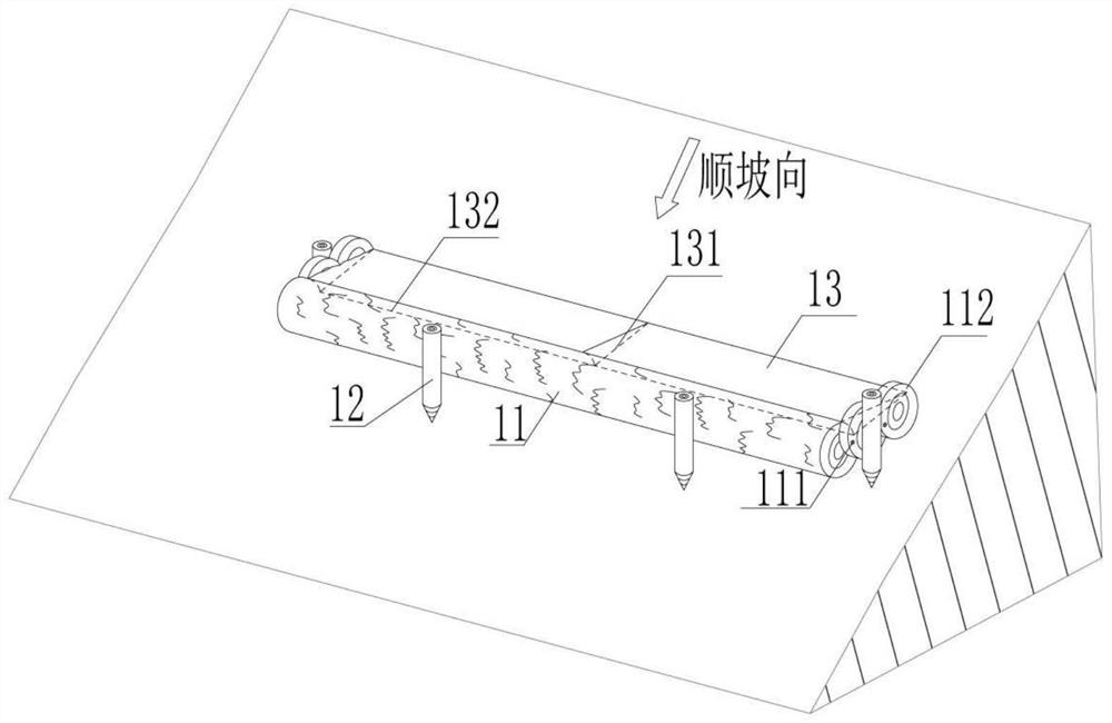
[0052] Slope protection measures include slope log interception devices and vegetation slope protection measures.

[0053] Slope log interception device such as figure 1 As shown, it is generally placed on the slope in the debris flow basin, and the tree trunks that h...


PUM


Abstract

The invention provides a device and a method suitable for comprehensive treatment of post-fire debris flow of a burned area. The slope protection measures aim at the upstream slope of the burnt area debris flow basin, grass seeds are sown through an unmanned aerial vehicle or manpower, trees are planted manually, and water and soil loss is reduced. Meanwhile, log trunks and treetops are used for manufacturing a simple slope surface blocking device, and slope surface erosion is weakened. The material source cleaning measure aims at the whole area of debris flow of the burned area, and burnout tree branches are transferred to a safety zone and prevented from participating in debris flow starting. In the branch ditch blocking measure, a log residue blocking device is arranged in an upstream ditch channel, and most dry branches and fallen leaves in the ditch channel are blocked; the simple check dam is arranged in main and branch ditches in the middle and upper stream in the drainage basin to intercept most solid substances in the middle and upper stream. A conventional debris flow treatment method is used as a main ditch downstream treatment measure, and a silt arrester and a grit chamber are included. The method is simple to operate and easy to understand, most engineering raw materials can be obtained on site, the construction difficulty is small, cost is saved, and the method is environmentally friendly.

Description

technical field [0001] The invention relates to the field of prevention and control of post-fire debris flow disasters, in particular to a device and method suitable for comprehensive treatment of post-fire debris flow in burned areas. Background technique [0002] Post-fire debris flow is a common geological disaster that occurs after forest fires in densely vegetated mountainous areas. It is closely related to fire behavior in terms of disaster mechanism, susceptibility evaluation, and developmental characteristics. Forest fires often increase the possibility of debris flows in the trenches in the burned areas, posing a greater threat to villages, roads and buildings at the mouth of the trenches. The first rainy season after a forest fire is usually the most prone period for post-fire debris flows, so the prevention and control of post-fire debris flows should be as quick as possible. Conventional debris flow control measures and implementation methods require a long time...

Claims


Application Information

Patent Timeline
IPC IPC(8): E02B7/04E02B7/00A01G20/00A01G17/00
CPCE02B7/04E02B7/00A01G20/00A01G17/005
Inventor 胡卸文金涛白金钊冯潇段雯超周永豪吴建利王严杨瀛曹希超周瑞宸
Owner SOUTHWEST JIAOTONG UNIV
Why Eureka
Try Eureka