
Digital 3D optical variable image making process and laser photocomposition system

A production method and imaging system technology, applied in 3D image processing, image data processing, instruments, etc., can solve the problems of optically variable image difficulties, manual operation, high production costs, etc., achieve rich expression ability and increase production speed Effect

Inactive Publication Date: 2004-05-26
湖北强大包装实业有限公司
View PDF0 Cites 2 Cited by
  • Summary
  • Abstract
  • Description
  • Claims
  • Application Information

AI Technical Summary

Problems solved by technology

[0003] At present, there are mainly the following ways to make three-dimensional and optically variable images. One is to record holograms that form two-dimensional or three-dimensional images by light interference on a holographic dry plate. It is very difficult to obtain an optically variable image with high precision and dynamic effects; the other is laser direct writing, in which a computer controls the movement of a fine laser beam on the sample stage, and directly exposes on the surface of the photoresist to carve a continuous relief structure. A single-beam direct writing method has high requirements for electronic control and mechanical precision. If a grating of 10 mm × 10 mm is designed, the diameter of the focal point of the beam is 1 micron, and the operating speed is 10 mm / s. It takes at least 80 minutes for a 500 line / mm grating. For optically variable images with smaller grating constants and larger areas (such as optically variable images used for laser anti-counterfeiting packaging materials), single laser direct writing is obviously not suitable; The third is electron beam exposure. Although the grating precision of electron beam lithography is higher, its production cost is too high and the time is longer, and it is not feasible to obtain large-area three-dimensional and optically variable images.
For this reason, the inventor proposed a new production method in another patent application for the production method of an optically variable image and its phototypesetting system, that is, using an interference-type optical head as a laser direct writing head, and using a laser interference fringe image The pixels are used as laser direct writing points to realize the production of pixel gratings. Since one interference fringe pixel contains dozens of grating lines, it is dozens of times faster than the single-beam laser direct writing method, and can be used to design and manufacture larger areas. At the same time, the fringe density of the pixel grating can be higher, and a 10 mm × 10 mm grating is also designed. If the diameter of the focal point of the beam is 0.04 mm, and the operating speed is set to 80 dots / second, it takes more than 15 Minutes, significantly faster than single-beam direct writing, making large-area production possible; however, due to the running time limit of mechanical movement, for an area of ​​500 mm × 500 mm, it takes more than 400 hours. As a large-area application, the time is still It is unacceptable. On the other hand, in order to improve the resolution, the diameter of the beam needs to be reduced, which will lead to the reduction of the intersection area of ​​the two beams. Generally, when the spot diameter is 10 microns, the Vibrating up and down will seriously affect the overlapping degree of the two spots. Therefore, the highest image resolution of the system is 2540dpi
[0004] Considering the above-mentioned schemes, we found that in order to solve the problem of manual operation in holography, the subsequent methods are all made by single-point processing of interference fringes or unit grating points, which leads to slow speed. The main reason why it is difficult to make large-area images, if computer control can be used to realize the simultaneous production of multiple pixel raster points in the same image, the production speed will be greatly improved

Method used


Image

  • Digital 3D optical variable image making process and laser photocomposition system
  • Digital 3D optical variable image making process and laser photocomposition system
  • Digital 3D optical variable image making process and laser photocomposition system

Examples


Embodiment 1

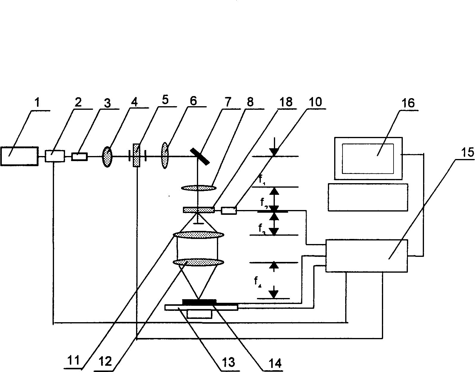
[0038] Embodiment one: see attached figure 2 As shown, a method for making digital three-dimensional and optically variable images, the image is decomposed into at least two sub-images according to the orientation and space frequency of the unit gratings, and the orientation and space frequency of the unit gratings in each sub-image are the same, and one of the sub-images is The image is input to the spatial light modulator, and a parallel light beam is modulated by the spatial light modulator 5 and imaged on the holographic optical element 18 to generate a diffracted beam, which is converged on the recording material 14 to generate the sub-image Corresponding to the image composed of multiple diffraction gratings, different sub-images are sequentially input to the spatial light modulator 5, and at the same time, the holographic optical element 18 is rotated or the position of the holographic optical element 18 is changed until the entire image is produced.

[0039] A laser p...

Embodiment 2

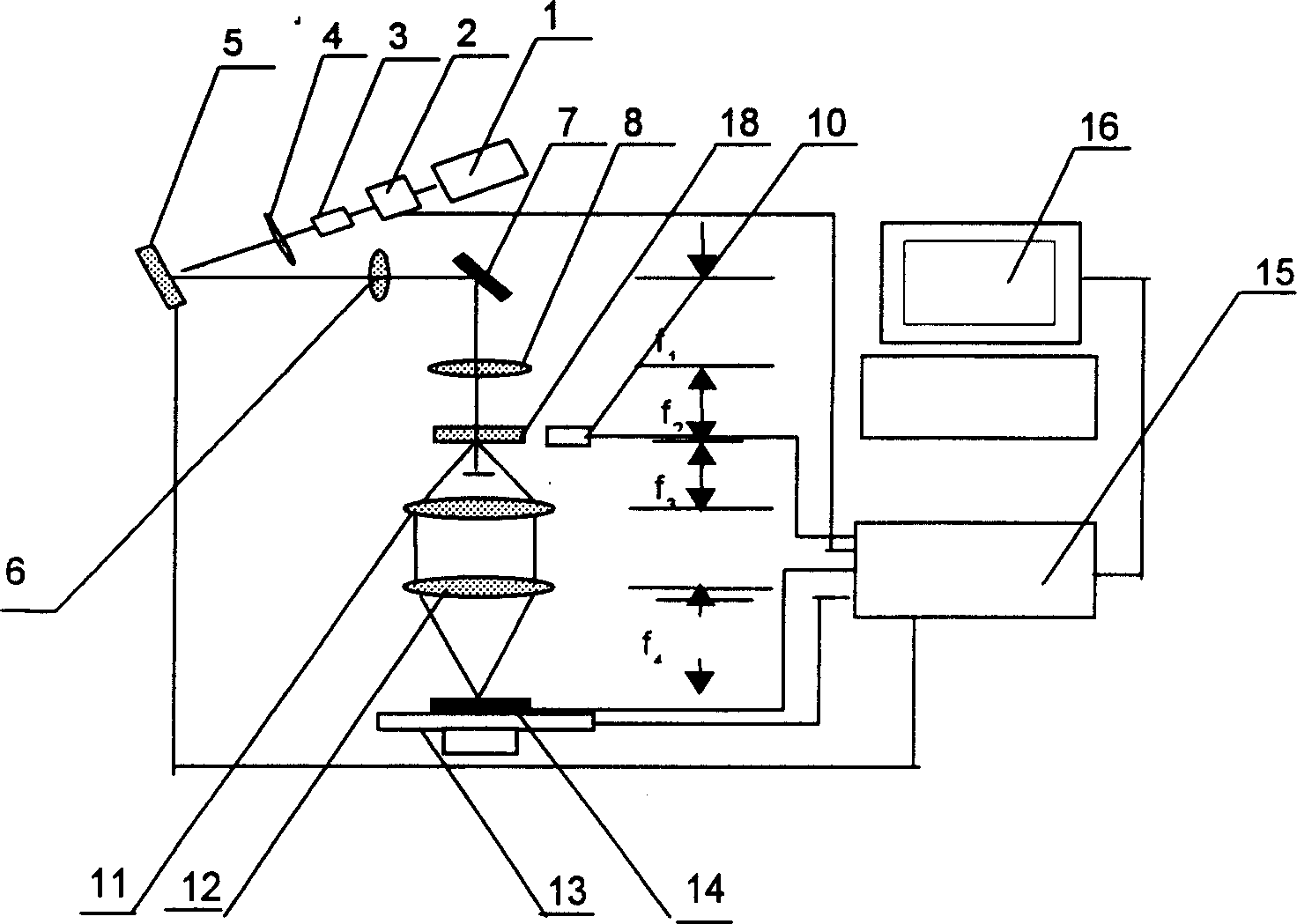
[0042] Embodiment two: see attached image 3 As shown, a method for making a digital three-dimensional and optically variable image first divides the image into multiple small-area images by geometric segmentation, and decomposes each small-area image into sub-images. For each sub-image, according to Embodiment 1 Made in the same steps.

[0043] The overall structure of the laser phototypesetting system of this embodiment is similar to that of Embodiment 1, wherein the spatial light modulator 5 is a reflective spatial light modulator, and the workbench 13 can move along the X-axis and the Y-axis, controlled by the computer 16 through the control system 15 The movement of the workbench 13 is controlled to drive the recording material 14 to move, and each small-area image is sequentially produced, thereby splicing into a whole image.

Embodiment 3

[0044] Embodiment three: see attached Figure 5 As shown, a laser phototypesetting system for making digital three-dimensional and optically variable images, including a light source 1, a photoelectric switch 2, a beam expander 3, a collimator 4, a spatial light modulator 5, an imaging system before beam splitting, The beam splitting element 9, the optical path system composed of the beam splitting imaging system, the workbench 13 on which the recording material 14 is placed, and the control part including the computer 16, the spatial light modulator 5 is a transmission type spatial light modulator, and the The beam splitting element 9 is arranged on the turntable 10, the turntable 10 can rotate and move along the Z-axis direction, the recording material 14 is placed on the workbench 13 and is located on the focal plane of the imaging system after beam splitting; the light source 1 can be A laser light source or a line spectrum light source; the imaging system before beam spli...


PUM


Abstract

According to the orientation and spatial frequency of unit grating the image of decomposed into at least two subimages, the orientation and spatial frequency of unit grating of every subimage are identical, one subimage is inputted on the space light modulator, a parallel light beam is passed through the space light modulator and imaged on beam splitting element to produce split beam, and collected on the recording material to produce the image which is correspondeng to the described subimage and is formed from several diffraction grating, so that the different subimages are inputted into space light modulator in turn until the whole image is made. Its laser photocomposition system includes optical path system formed from parallel light source, space light modulator, imaging system and beam-splitting element, working tablet for placing recording material and control portion, the beam-splitting is positioned on the turnplate, and the recording material is positioned on the focal surface of imaging system.

Description

technical field [0001] The invention relates to a method for making digital three-dimensional and optically variable images and a laser phototypesetting system for realizing the method, which are used for making three-dimensional images and other images with optically variable characteristics. Background technique [0002] Digital three-dimensional and light-variable image is a new type of optical image, which is composed of pixel array, each pixel is a pixel grating (unit grating), the orientation and space frequency of the unit grating have infinite combinations, so that the image has The optical characteristics of various light-changing effects such as color change, dynamic effect and three-dimensional sense, the image can be very complex. For the relief-type image, it can be made into a reflective reproduction hologram through molded aluminum plating, and the human eye can directly face the image. The light source observes the reflected diffracte...

Claims


Application Information

Patent Timeline
Patent Type & Authority Patents(China)
IPC IPC(8): G03H1/12G03H1/22
Inventor 陈林森沈雁解剑峰陆志伟汪振华顾华俭吴建宏胡祖元胡元孙青
Owner 湖北强大包装实业有限公司
Learn More