
Electroluminescence element

An electroluminescent element and light-emitting layer technology, applied in electroluminescent light sources, electrical components, electric light sources, etc., can solve the problems of peeling off the moisture-proof film, separation of zinc ions, not being covered by the moisture-proof film 4A, etc. easy effect

Inactive Publication Date: 2004-12-01
PANASONIC CORP
View PDF0 Cites 0 Cited by
  • Summary
  • Abstract
  • Description
  • Claims
  • Application Information

AI Technical Summary

Problems solved by technology

[0010] However, the above conventional EL elements such as Figure 4 As shown in the partial cross-sectional view of (a), when the phosphor 4 is covered with a moisture-proof coating 4A such as titanium oxide, once a plurality of phosphors 4 aggregate, the aggregation boundary portion 9 may not be covered by the moisture-proof coating 4A.
or as Figure 4 As shown in (b), when the phosphor 4 and the resin 3 covered with the moisture-proof film 4A are stirred or transported in a state of being mixed into a paste in a solvent, the moisture-proof film 4 may be caused by the extrusion between the phosphors 4 Peel off, exposing phosphor 4
Due to the above reasons, problems such as the separation of zinc ions from the phosphor 4, the deterioration of the insulation of the light-emitting layer 5 in high humidity, and the appearance of black spots are prone to occur.
[0011] In addition, when the moisture-proof coating 4A is not a metal oxide but aluminum nitride or the like, even if the moisture-proof coating 4A is completely covered, the aluminum nitride will be hydrolyzed to produce ammonium ions in high humidity, and the ammonium ions are likely to cause the light-emitting layer 5 The problem of insulation deterioration of resin 3

Method used


Image

  • Electroluminescence element
  • Electroluminescence element
  • Electroluminescence element

Examples


Embodiment Construction

[0023] Implementation Status 1

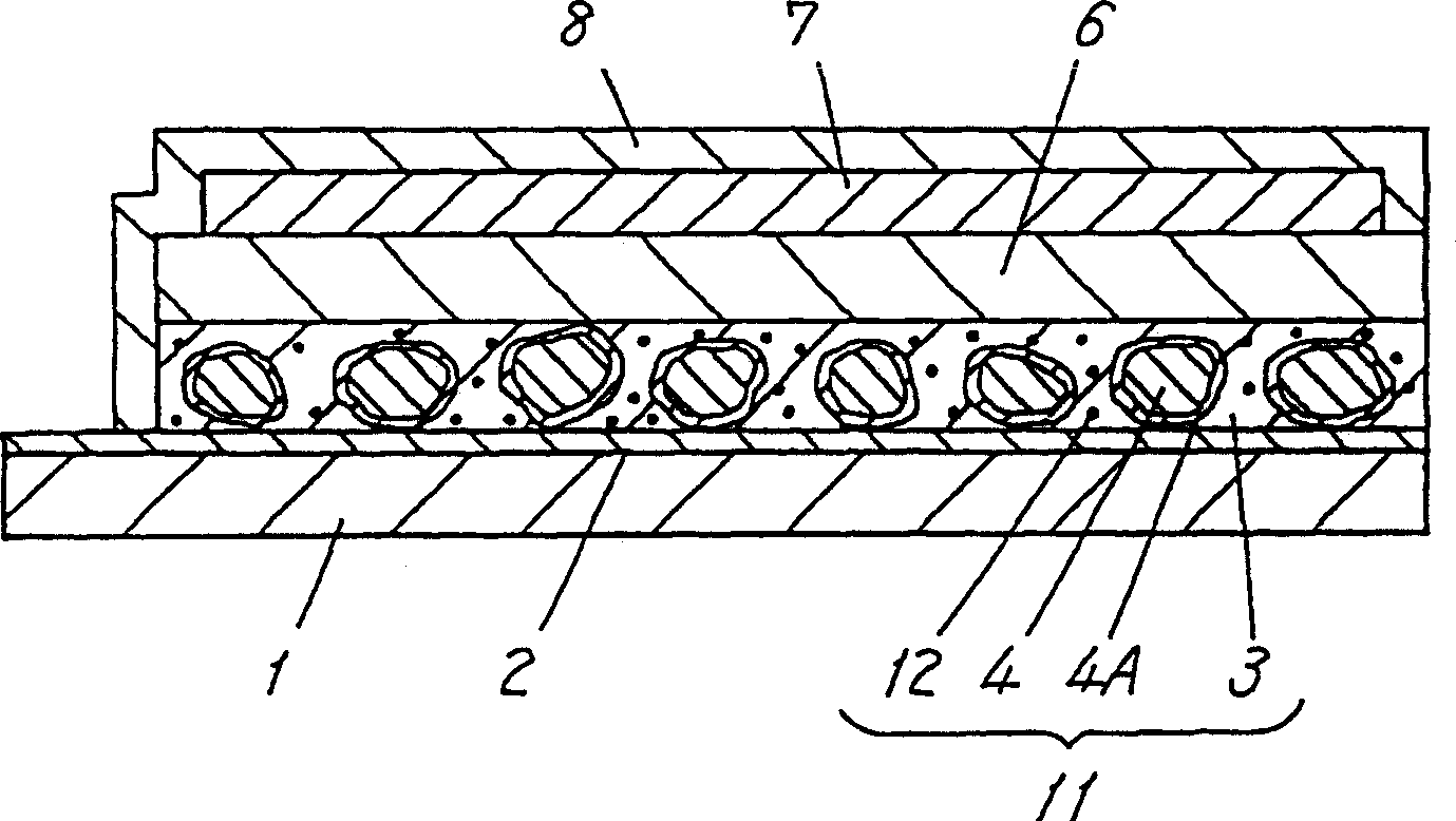
[0024] figure 1 It is a cross-sectional view of the EL element of Embodiments 2 and 1 of the present invention. figure 1 In this method, a light-transmitting electrode layer 2 composed of ITO is formed on the entire light-transmitting insulating film 1 such as polyethylene terephthalate or polyimide by a sputtering method or an electron beam method.

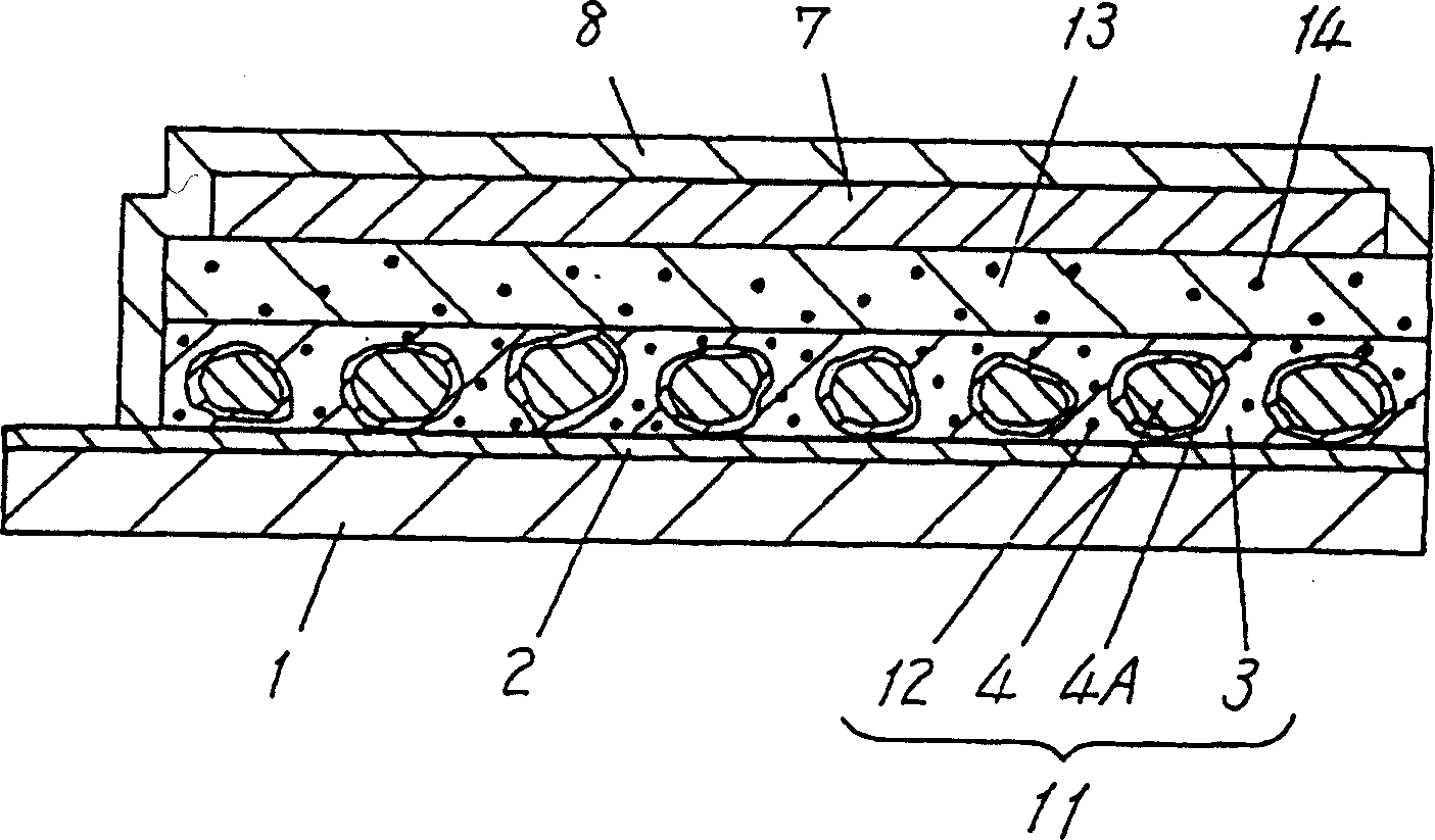
[0025] On the upper surface of the electrode layer 2 is formed a light-emitting layer 11 in which a phosphor 4 such as zinc sulfide as a light-emitting body is dispersed on a resin having a high dielectric constant such as fluorine-containing rubber or cyano resin. Metal oxides such as aluminum oxide, titanium oxide, and silicon oxide, and a moisture-proof coating 4A such as aluminum nitride are added to the phosphor 4 . Inorganic cation exchangers 12 such as antimony acid, phosphate, silicate, and zeolite are dispersed in the phosphor 4 in the light emitting layer 11 . That is, in the presen...


PUM


Abstract

An EL element comprising a light transmitting substrate, a light transmitting electrode formed on the substrate, a light emitting layer containing a positive ion absorber, a dielectric layer and a back electrode. Further, an EL element of the present invention contains a positive ion absorber in the dielectric layer. An EL element in accordance with an embodiment comprises a light emitting layer formed of a resin, a phosphor and a positive ion absorber, the positive ion absorber being 1 - 400 parts by weight to a 100 parts of the resin in the light emitting layer. An EL element in another embodiment comprises a dielectric layer formed of a resin, a high dielectric constant inorganic filler and a positive ion absorber, the positive ion absorber being 0. 5 - 50 to a 100 parts of a total amounts of the resin and the filler.

Description

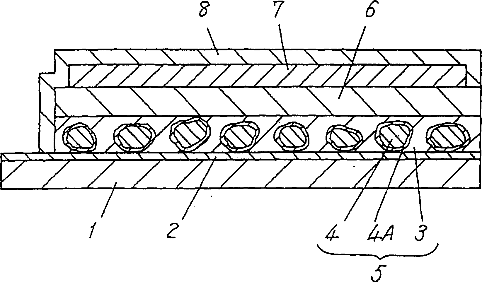
technical field [0001] The present invention relates to an electroluminescence (hereinafter referred to as EL) element used for illumination of a display portion and an operation portion of various electronic instruments, and the like. Background technique [0002] In recent years, with the diversification of various electronic devices, there has been an increase in the number of devices with backlights for illumination behind display screens and LCDs that allow the display to be recognized and operated even in a dark environment. Most of these backlights use EL elements. [0003] pass image 3 and Figure 4 A conventional EL element will be described. [0004] image 3 is a cross-sectional view of a conventional EL element. image 3 In this method, a light-transmitting electrode layer 2 composed of indium tin oxide (hereinafter referred to as ITO) is formed on the entire light-transmitting insulating film such as polyethylene terephthalate by a sputtering method or an ele...

Claims


Application Information

Patent Timeline
Patent Type & Authority Patents(China)
IPC IPC(8): H05B33/12H05B33/20H05B33/22
CPCH05B33/22Y10S428/917H05B33/20
Inventor 田边功二近久阳介西冈直弘
Owner PANASONIC CORP
Learn More