
Method for recovering catalytic reaction oil and gas heat energy and cooling

A technology for reacting oil and gas, oil and gas cooler, applied in non-catalytic thermal cracking, cracking, fluidized bed furnace, etc., can solve the problems of high temperature, complex process, low efficiency of heat energy recovery of high temperature oil and gas, etc.

Inactive Publication Date: 2005-02-16
SINOPEC ENG
View PDF4 Cites 2 Cited by
  • Summary
  • Abstract
  • Description
  • Claims
  • Application Information

AI Technical Summary

Problems solved by technology

If the conventional process is used to directly enter the fractionation tower, it will bring the following series of problems: (1) The material grade of the hot wall oil and gas pipeline and the lower part of the fractionation tower needs to be upgraded to stainless steel; (2) The condensation of high temperature oil and gas will lead to oil and gas pipelines and fractionation The coking of the system in the lower part of the tower hinders the long-term operation of the device; (3) The heat energy recovery efficiency of high-temperature oil and gas is low
Production of ethylene and steam cracking processes using naphtha and other light hydrocarbons as raw materials, although the boiler gas production scheme is used to cool down the oil and gas in terms of high-temperature oil and gas, but the investment is high, the process is complicated, the control is difficult, and it must be operated intermittently. It is difficult to match the medium and high pressure steam of the refinery with the utility system of the refinery
[0003] In recent years, some patents have introduced the process of catalytic pyrolysis, such as the patent CN1218786A named "method of catalytic pyrolysis to produce ethylene and propylene", and the patent CN1083092A named "method of catalytic pyrolysis of petroleum hydrocarbons". and the patent ZL97119048.8 titled "Direct Conversion of Multiple Feed Hydrocarbons to Olefins", both of which are processes for producing olefins from various petroleum fractions and hydrocarbons, including detailed descriptions of the catalysts, reaction conditions and Main reaction regeneration flow process etc., but all do not propose the concrete technical scheme that the inventive method will narrate in detail to solve the above-mentioned problem
At the same time, related patents also include the patent CN1055380A named "catalytic cracking with quenching" and the patent CN1254362A named "quick cooler". The former belongs to the process of conventional catalytic cracking reaction quenching to reduce thermal cracking and increase the target product, and the latter belongs to steam cracking The equipment patents for the purpose of cooling oil and gas through shell-and-tube partition wall heat exchange to generate steam to achieve the purpose of cooling also do not propose specific technical solutions to the above-mentioned problems that will be described in detail in the method of the present invention below

Method used


Image

  • Method for recovering catalytic reaction oil and gas heat energy and cooling
  • Method for recovering catalytic reaction oil and gas heat energy and cooling

Examples


Embodiment

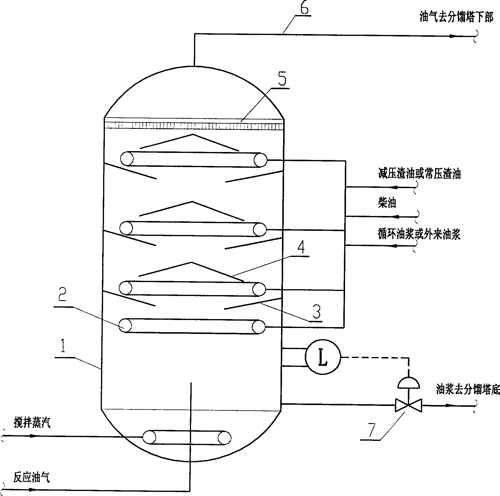
[0012] This technical solution was applied to the 55,000 tons / year catalytic pyrolysis industrial test device. The test was run for two and a half months. 640°C, the oil-gas temperature after being cooled by the oil-gas cooler is shown in Table 1.

[0013] project

First group

Second Group

The third group

Fourth group

Riser outlet temperature, ℃

644

610

611

602

Settler dilute phase temperature, ℃

618

578

582

580

Cooler upper temperature, ℃

245

237

230

228

Cooler middle temperature, ℃

251

233

231

266

Lower temperature of cooler, ℃

295

302

296

321

Cooler outlet oil gas temperature, ℃

276

277

274

313

Cooler differential pressure, kPa

14.3

15.5

16.5

11.9

Fractionation ...


PUM


Abstract

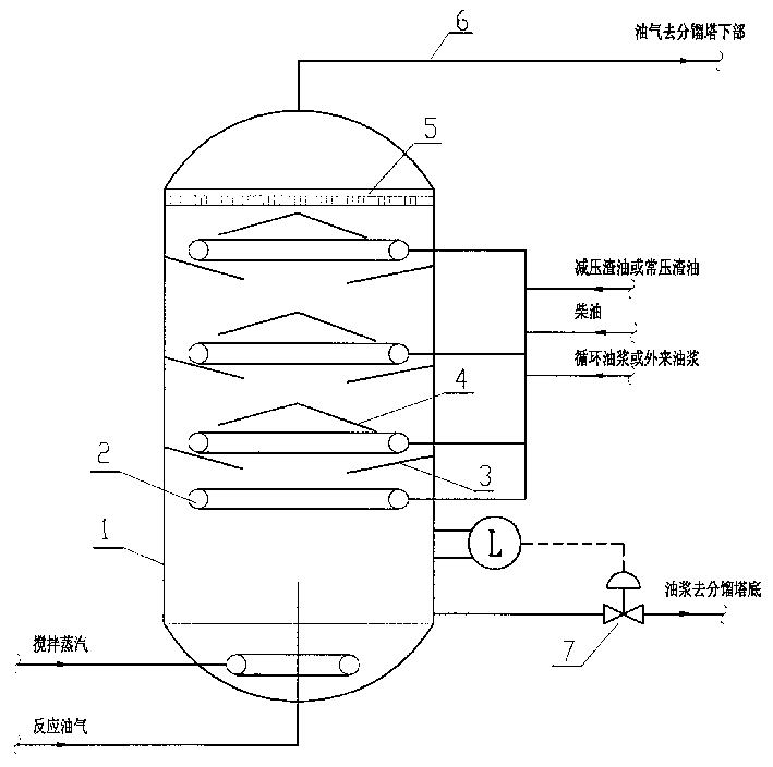
A process for cooling the oil vapour at 580-670 deg.c during catalytic cracking reaction and recovering its heat energy is characterized by use of an oil vapour cooler arranged on the top of reaction settling unit. Said cooler contains multiple layers of shaped baffle and the cooling liquid medium and counter-flow high-temp oil vapour for direct contact. Its advantage is high heat exchange efficiency.

Description

technical field [0001] The invention belongs to the heat energy recovery and cooling method of catalytic reaction oil gas, more specifically, it is a heat energy recovery and rapid cooling method for catalytic thermal cracking and similar process reaction oil gas. Background technique [0002] The reaction oil gas of the conventional heavy oil catalytic cracking process does not need to be cooled, and directly enters the fractionation tower, and the heat of the oil gas is taken away by the oil slurry circulation of the fractionation tower. The reaction oil gas system has no heat energy recovery and cooling measures, and its oil gas pipeline and fractionation tower can be used Carbon steel material. Different from the conventional heavy oil catalytic cracking process, catalytic thermal cracking is a process for producing ethylene and propylene products from heavy oil, and its reaction temperature is as high as 580-670°C, which is 100-150°C higher than the conventional catalyt...

Claims


Application Information

Patent Timeline
IPC IPC(8): C10G9/04F27B15/16
Inventor 郭志雄吴雷余龙红鞠林青房家贵黄荣臻
Owner SINOPEC ENG
Learn More