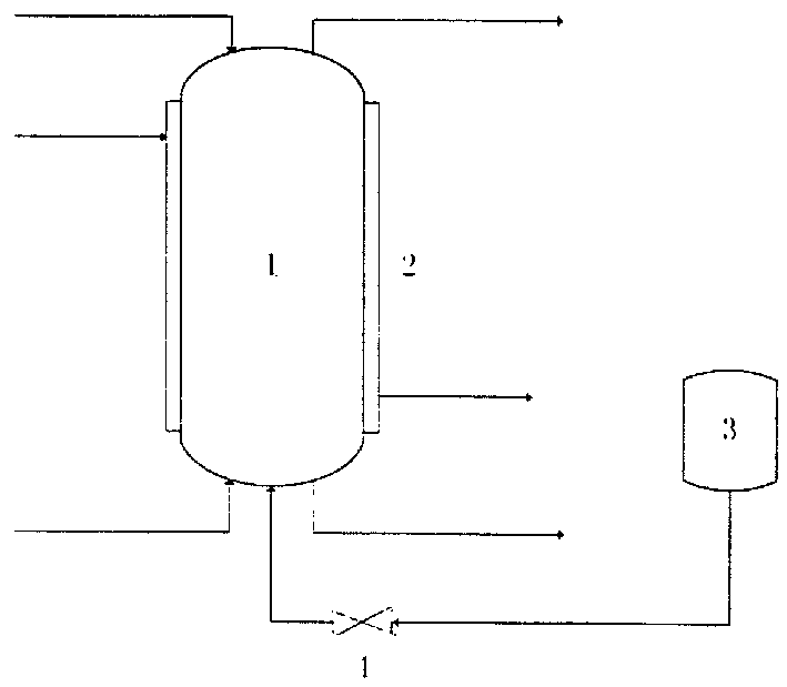
Pulse tower for extraction
A pulse tower and extraction technology, which is applied in the field of pulse towers, can solve the problems of large resistance loss, high external energy consumption, and easy occurrence of liquid flooding in the pulse extraction tower, and achieves less environmental impact, less solvent leakage, and less liquid flooding. Effect
- Summary
- Abstract
- Description
- Claims
- Application Information
AI Technical Summary
Problems solved by technology
Method used
Image


Examples
Embodiment 1
[0033] The wastewater of a factory contains 6.5% caprolactam and some solid coke (about 3% when the solid content is high), and the viscosity of the wastewater is also relatively large. In order to reclaim the caprolactam in the above-mentioned waste water, benzene is used as a solvent for extraction (the reason for choosing benzene is that a large amount of benzene must be used as raw material in the production of this factory, and there is already a ready-made benzene distillation tower, so it is not necessary to build a benzene distillation tower after extraction. recovery solvent benzene). The pulse sieve tray tower in this patent is now used, wherein the effective height of the sieve tray tower is 6m, and the inner diameter of the tower is 600mm. The pulse generator adopts a rotary valve-circulation pump pulse generator (see Simons A J F. Pulsed Packed Columns, in Handbook of Solvent Extraction, Edited by Lo T C, Baird M H I, Hanson C. New York: John Wiley & Sons, 1983, ...
Embodiment 2
[0038] The ammonium sulfate aqueous solution of a certain factory contains about 1% caprolactam. In order to recover the caprolactam in the aqueous solution, benzene is used as solvent for extraction (the reason for choosing benzene is that a large amount of benzene must be used as raw material in the production of the factory, and there is already a ready-made benzene distillation tower , so it is not necessary to build a benzene distillation tower after the extraction to recover the solvent benzene). The pulse packed tower in this patent is now used, wherein the inner diameter of the tower is 800mm, the effective height of the packed tower is 6.5m, and the packing layer is divided into 3 sections, which are 2m in the lower part of the tower (using 250Y stainless steel plate wave structured packing) and 2m in the middle of the tower ( Raschig ring packing is used), the upper part of the tower is 2.5m (Raschig ring packing is used), and empty tower sections are left between eac...
PUM
 Abstract
Description
Claims
Application Information