
Catalytic membrane reactor with two component three dimensional catalysis

A catalytic membrane reactor, catalyst technology, applied in the reaction of gas and gas under the catalytic active body, chemical/physical/physicochemical fixed reactor, heterogeneous catalyst chemical elements, etc., can solve the problem of affecting reaction products, etc. question

Inactive Publication Date: 2001-01-17
ELTRON RES
View PDF11 Cites 15 Cited by
  • Summary
  • Abstract
  • Description
  • Claims
  • Application Information

AI Technical Summary

Problems solved by technology

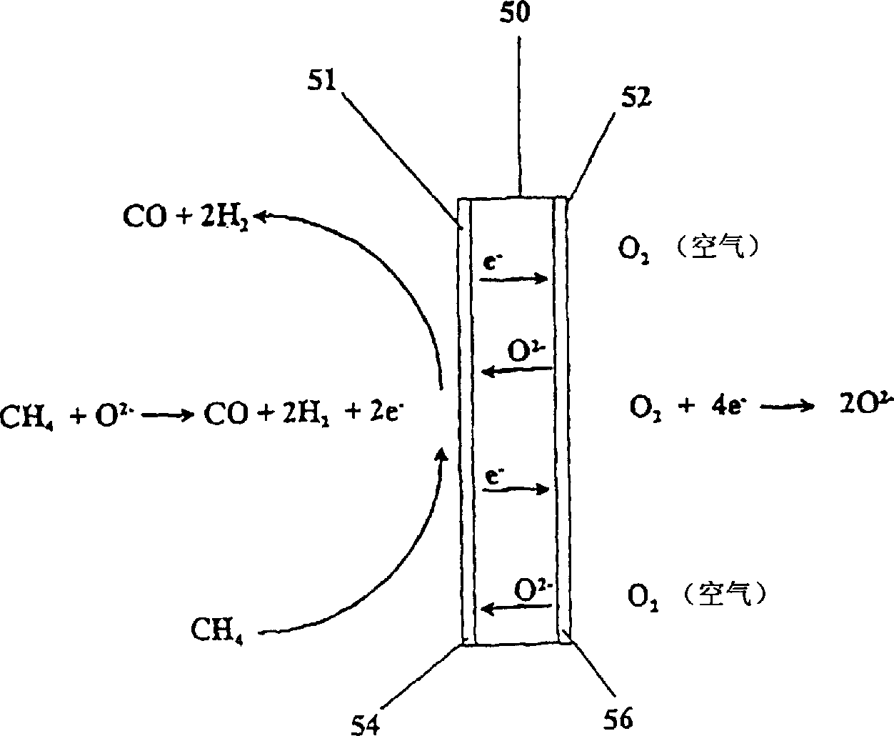
[0012] One problem with ceramic membrane reactors is that the membrane material itself may be catalytically active to oxygen ions, changing the specific types of oxygen species available for membrane surface reactions, thus affecting the reaction products

Method used


Image

  • Catalytic membrane reactor with two component three dimensional catalysis
  • Catalytic membrane reactor with two component three dimensional catalysis
  • Catalytic membrane reactor with two component three dimensional catalysis

Examples


Embodiment 1

[0111] Example 1: Production of synthesis gas in a reactor with and without bonded catalyst layers.

[0112] By chemical formula Sr 1.7 La 0.3 Ga 0.6 Fe 1.4 o 5.15 A single-phase material for the fabrication of tubular membranes with one end closed. The powder of this composition is firstly prepared by conventional solid-state synthesis method, specifically as described in PCT / US96 / 14841 and Example 5. This single-phase powder was pressed into a tube shape by isostatic pressing method, followed by sintering to obtain a dense and strong tubular membrane. The grinding and sintering steps can be repeated, if desired, to ensure that the material is a single phase prior to isostatic pressing to form the tube.

[0113] Coating a layer of La on the inner surface (reducing surface) of the tubular membrane 0.8 Sr 0.2 CoO 3 (LSC) used as an oxidation / reduction catalyst; or coated with a metal on the oxidation / reduction catalyst, such as 5% by weight Pd on LSC.

[0114] The ou...

Embodiment 2

[0119] Example 2: Syngas Production in Reactors with and without Packed Bed Catalysts

[0120] Same as embodiment 1, by chemical formula Sr 1.7 La 0.3 Ga 0.6 Fe 1.4 o 5.15 A single-phase material for the fabrication of tubular membranes with one end closed.

[0121] A layer of La was coated on the inner surface of the tubular membrane 0.8 Sr 0.2 COO 3 (LSC) was used as a redox catalyst. Adhesive catalyst coated on the outer surface of the tubular membrane: at La 0.8 Sr 0.2 MnO 3 Ni on (20% by weight).

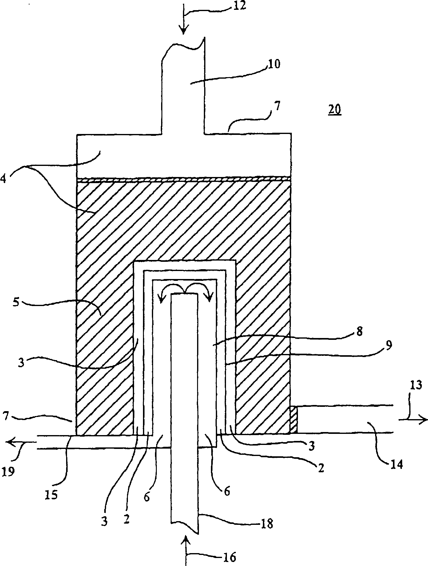
[0122] exist figure 1 The synthesis gas reactor shown compares tubular membranes. One reactor is supplied with Al in its oxidation zone 2 o 3 A packed bed of granules that were previously coated with La 0.8 Sr 0.2 MnO 3 Powder with Ni (10% by weight) on top: while one reactor had no packed bed. In both cases, air was used as the oxygen-containing gas passing through the interior of the tubular membranes and an 80% by volume methane mixture in helium was used ...

Embodiment 3

[0126] Example 3: Syngas production in reactors with different bonded catalyst layers

[0127] As described in Example 1, by chemical formula Sr 1.7 La 0.3 Ga 0.6 Fe 1.4 o 5.15 A single-phase material for the fabrication of tubular membranes with one end closed.

[0128] The inner surface of the tubular membrane is coated with a layer of La 0.8 Sr 0.2 COO 3 Used as a redox catalyst.

[0129] The outer surface of a tubular membrane is coated with La 0.8 Sr 0.2 MnO 3 . The outer surface of another tubular membrane was coated with La with Ni (20% by weight) on it. 0.8 Sr 0.2 MnO 3 . These two catalysts were used as the bonded catalyst layers on the oxidized surfaces of the two membranes, respectively.

[0130] in such as figure 1 The synthesis gas reactor shown compares tube membranes with different bonded catalyst layers. In both cases, the reactor was supplied with Al coated with Ni (5% by weight) in its oxidation zone. 2 o 3 Particle packed bed. Both used ...


PUM


Abstract

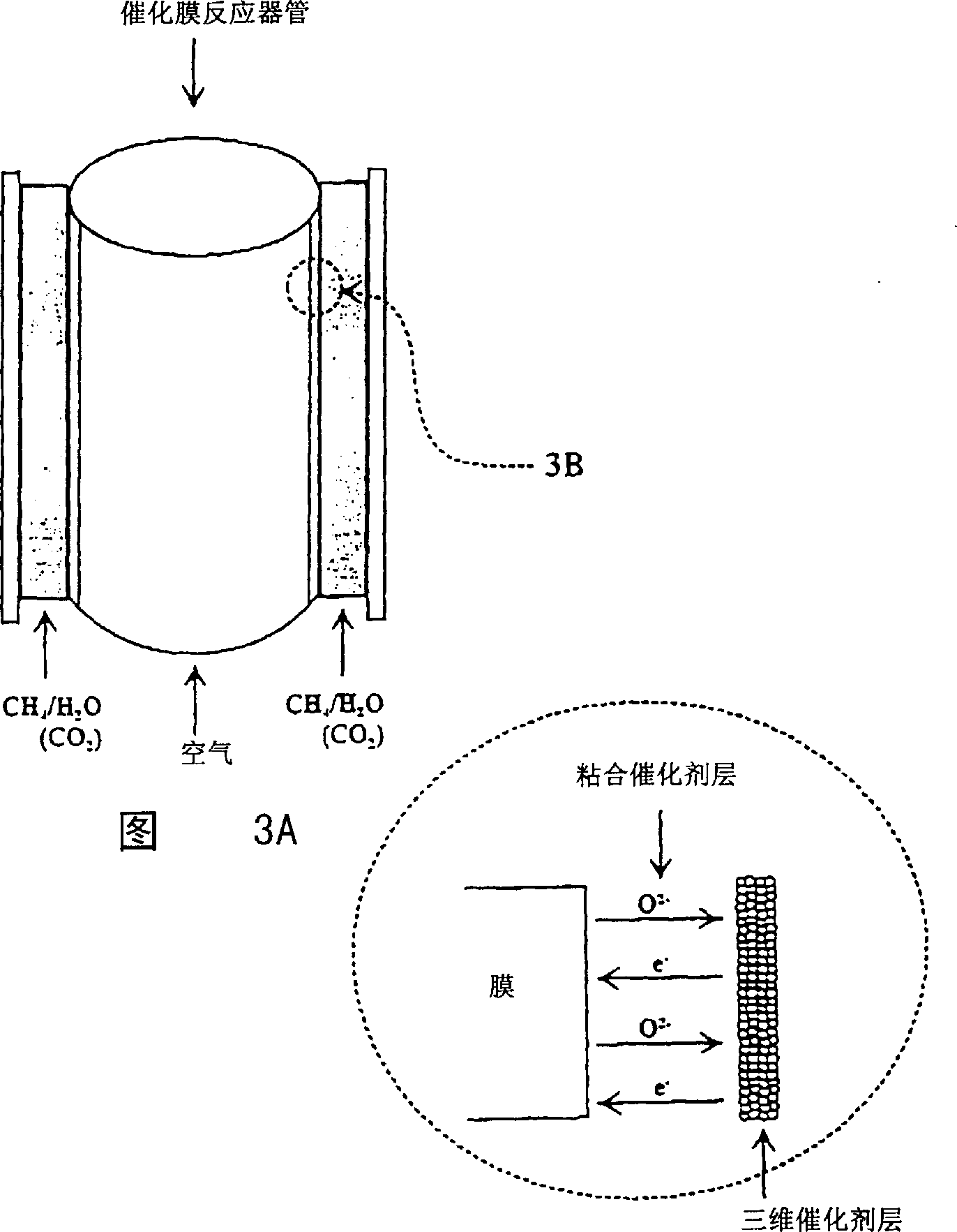
This invention relates to catalytic reactor membranes having a gas-impermeable membrane (2) for transport of oxygen anions. The membrane (2) has an oxidation surface and a reduction surface. The membrane (2) is coated on its oxidation surface with an adherent catalyst layer and is optionally coated on its reduction surface with a catalyst that promotes reduction of an oxygen-containing species (e.g., O2, NO2, SO2, etc.) to generate oxygen anions on the membrane. The reactor (20) has an oxidation zone (4) and a reduction zone (6) separated by the membrane (2). A component of an oxygen-containing gas in the reduction zone (6) is reduced at the membrane (2) and a reduced species in a reactant gas in the oxidation zone (4) of the reactor is oxidized. The reactor (20) optionally contains a three-dimensional catalyst (5) in the oxidation zone (4). The adherent catalyst layer and the three-dimensional catalyst (5) are selected to promote a desired oxidation reaction, particularly a partial oxidation of a hydrocarbon. Preferred membrane materials of this invention are mixed metal oxides which are derived from brownmillerite and can, themselves, have brownmillerite structure. In a preferred embodiment, the oxygen reduction catalyst is Pd (5% by weight) on La0.8Sr0.2CoO3-x. The adherent catalyst layer is Ni (20% by weight) on La0.8Sr0.2MnO3 and the three-dimensional catalyst is Ni (5% by weight) on alumina.

Description

field of invention [0001] This invention relates to the catalytic partial and complete oxidation of hydrocarbons and related reducing species using catalytic membrane reactors. The disclosed reactor has a gas impermeable solid state membrane with a bonded catalyst layer on it used in conjunction with a fixed bed (or packed bed) of catalyst. Select membrane material, catalyst layer and fixed bed (or packed bed) catalyst to achieve the required selective oxidation reaction. Catalytic membrane reactions include the partial oxidation of methane or natural gas to synthesis gas. The present invention also relates to methods for the oxidation of reactant gases and the reduction of oxygen-containing gases using a catalytic membrane reactor. Background of the invention [0002] In the past, catalytic membrane reactors employing solid-state membranes for oxidizing or decomposing various chemical substances have been studied and used. A valuable potential use of such reactors is in ...

Claims


Application Information

Patent Timeline
Patent Type & Authority Applications(China)
IPC IPC(8): B01D53/22B01D53/32B01D71/02B01J4/04B01J8/00B01J8/02B01J12/00B01J19/00B01J19/24B01J23/00B01J23/83B01J23/89B01J35/00B01J35/06C01B3/36C01B3/38C01B13/02C01B17/04C01C3/02H01M8/12
CPCC01B17/0465B01J23/8946H01M4/9066Y02E60/521B01J23/002B01J2219/00051B01J23/83C01B13/0255C01B2203/1052B01J2208/00601B01J35/0033B01D2323/08B01J12/007C01C3/0216H01M8/1206C01B2203/1064B01D2325/18B01J2219/00063C01B2203/1041B01J8/009C01B3/36C01B2203/1082B01J35/065C01B2203/1258B01D53/326B01D53/228B01D2325/10B01D2323/12B01J8/0278B01D71/024C01B2203/1035H01M8/1246C01B2203/1241C01B3/386B01D67/0041B01D69/141B01J2219/0018C01B2203/1011B01J2219/00189C01B2203/0261Y02E60/525C01B2210/0046H01M4/9033B01J19/2475B01J2523/00H01M8/1231Y02P20/52Y02E60/50Y02P70/50B01J35/33B01J35/59B01J2523/24B01J2523/3706B01J2523/845B01J2523/32B01J2523/842B01J2523/72B01J2523/31B01J23/8892C01B3/38C01B2203/1058
Inventor M·施瓦茨J·H·怀特A·F·萨米尔
Owner ELTRON RES
Learn More