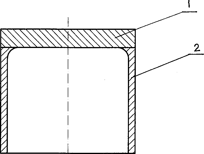
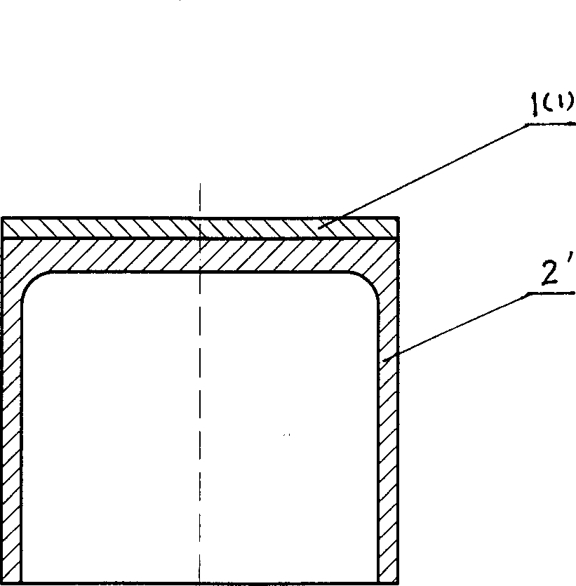
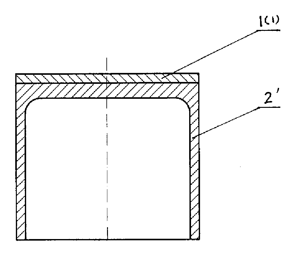
Engine valve guide tube of composite powder metallurgy material and its manufacture
An engine valve and composite material technology, which is applied to engine components, machines/engines, mechanical equipment, etc., can solve the problems that the valve cannot be opened and closed normally, affect the performance of the engine, and the utilization rate of materials is low, so as to save the machining process. , the effect of material saving and simple preparation method
- Summary
- Abstract
- Description
- Claims
- Application Information
AI Technical Summary
Problems solved by technology
Method used
Image
Examples
Embodiment 1
[0043] ——Prepare powder material A according to the following components and their mass percentage content:
[0044] Composition Particle size Mass percentage dosage
[0045] Iron powder ≤147 83%
[0046] Copper powder ≤74 0.5%
[0047] Nickel powder 2 2.0%
[0048] Molybdenum powder ≤74 0.5%
[0049] Graphite powder ≤74 1.0%
[0050] Ferrophosphorus powder ≤74 2.4%
[0051] Niobium carbide powder 4 10%
[0052] Acla powder ≤38 0.6% Prepare powder material B according to the following components and their mass percentages:
[0053] Composition Particle size Mass percentage dosage
[0054] Iron powder ≤147 76%
[0055] Copper powder ≤74 2.0%
[0056] Nickel powder 2 2.0%
[0057] Molybdenum powder ≤74 1.0%
[0058] Graphite powder ≤74 1.0%
[0059] Phosphorus iron or phosphor copper powde...
Embodiment 2
[0069] ——Prepare powder material A according to the following components and their mass percentage content:
[0070] Composition Particle size Mass percentage dosage
[0071] Iron powder ≤147 75%
[0072] Copper powder ≤74 2.0%
[0073] Nickel powder 2 3.0%
[0074] Molybdenum powder ≤74 0.9%
[0075] Graphite powder ≤74 0.8%
[0076] Phosphor copper powder ≤74 4.5%
[0077] Niobium carbide powder 4 12%
[0078] Akela powder ≤38 0.8% Prepare powder material B according to the following components and their mass percentages:
[0079] Composition Particle size Mass percentage dosage
[0080] Iron powder ≤147 65%
[0081] Copper powder ≤74 4.0%
[0082] Nickel powder 2 3.0%
[0083] Molybdenum powder ≤74 2.0%
[0084] Graphite powder ≤74 0.5%
[0085] Phosphorus iron or phosphor copper powd...
Embodiment 3
[0094] ——Prepare powder material A according to the following components and their mass percentage content:
[0095] Composition Particle size Mass percentage dosage
[0096] Iron powder ≤147 86%
[0097] Copper powder ≤74 1.5%
[0098] Nickel powder 2 1.0%
[0099] Molybdenum powder ≤74 1.0%
[0100] Graphite powder ≤74 0.5%
[0101] Phosphor copper powder ≤74 4.5%
[0102] Niobium carbide powder 4 5.0%
[0103] Acla powder ≤38 0.5% Prepare powder material B according to the following components and their mass percentages:
[0104] Composition Particle size Mass percentage dosage
[0105] Iron powder ≤147 78%
[0106] Copper powder ≤74 2.2%
[0107] Nickel powder 2 4.0%
[0108] Molybdenum powder ≤74 1.5%
[0109] Graphite powder ≤74 1.5%
[0110] Ferrophosphorus powder ≤74 2.0%
[...
PUM
| Property | Measurement | Unit |
|---|---|---|
| thickness | aaaaa | aaaaa |
| hardness | aaaaa | aaaaa |
Abstract
Description
Claims
Application Information
 - R&D
- Intellectual Property
- Life Sciences
- Materials
- Tech Scout
- Unparalleled Data Quality
- Higher Quality Content
- 60% Fewer Hallucinations
Browse by: Latest US Patents, China's latest patents, Technical Efficacy Thesaurus, Application Domain, Technology Topic, Popular Technical Reports.
© 2025 PatSnap. All rights reserved.Legal|Privacy policy|Modern Slavery Act Transparency Statement|Sitemap|About US| Contact US: help@patsnap.com


