

Secondary-emission rare earth-molybdenum material and its preparing process
An emissive material, secondary technology, applied in the direction of electrical components, exhaust connections/feeds, gas discharge tubes/containers, etc.
- Summary
- Abstract
- Description
- Claims
- Application Information
AI Technical Summary
Problems solved by technology
Method used
Image

Examples
example 1
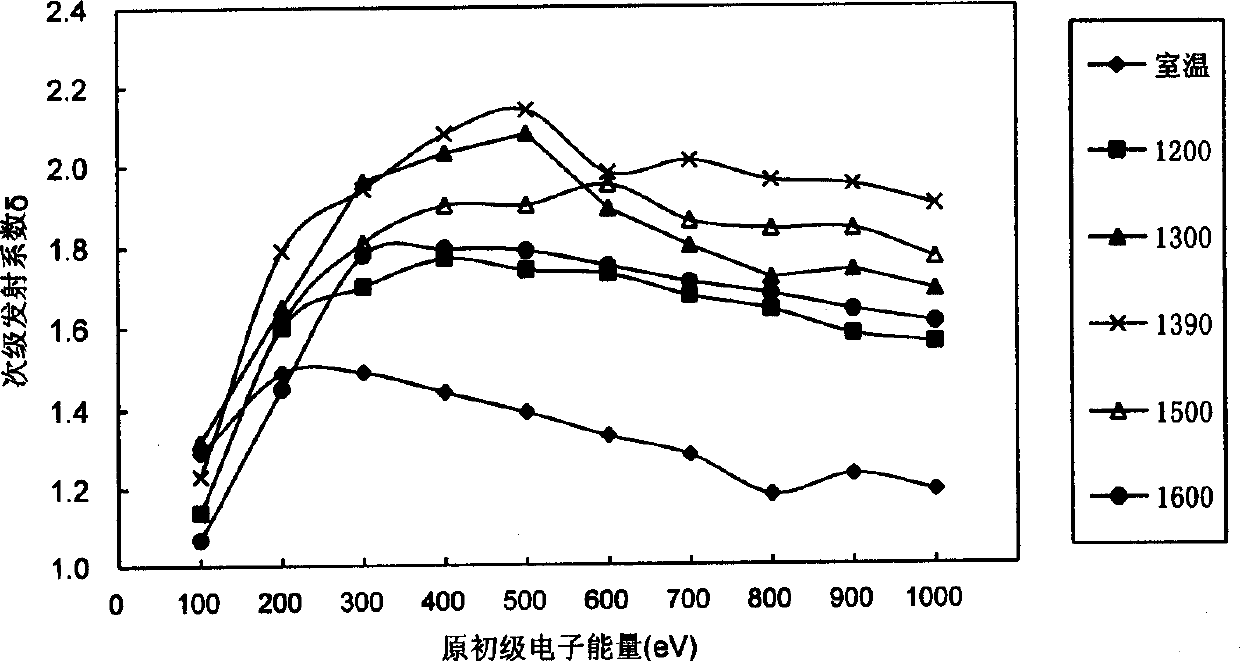
[0013] Example 1, 3.32 grams of lanthanum nitrate and 11.07 grams of yttrium nitrate were dissolved in water respectively, and added to 120.02 grams of powdered MoO 2 in (where La 2 o 3 Accounting for 2.5% by weight of molybdenum, Y 2 o 3 The weight ratio of molybdenum is 7.5%), the doped MoO 2 The powder is kept at 500°C under hydrogen for 2 hours to decompose rare earth nitrates into rare earth oxides, and then doped MoO in a multi-stage hydrogen furnace at 800-1000°C 2 Powder reduced to doped La 2 o 3 and Y 2 o 3 The composite rare earth aluminum powder is made into a rare earth molybdenum rod with a certain size after pressing and sintering. After machining, a rare earth molybdenum sheet of φ10×1mm is made. Then laser welding is used to weld the rare earth molybdenum sheet with the molybdenum cylinder and the metal tungsten wire used for heating, and after exhausting and activation treatment, the rare earth molybdenum experimental magnetron is made. The secondary...
example 2
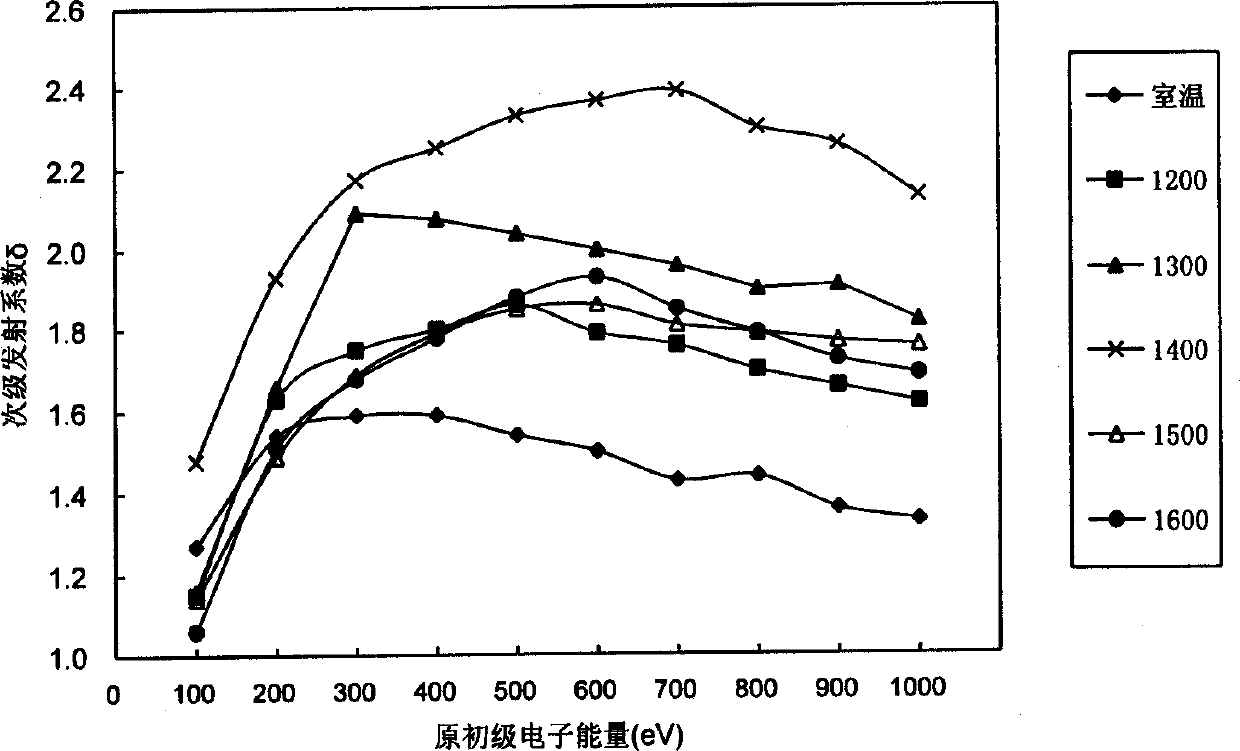
[0014] Example 2, 4.98 grams of lanthanum nitrate and 16.60 grams of yttrium nitrate were dissolved in water respectively, and added to 113.35 grams of powdered MoO 2 in (where La 2 o 3 The weight ratio of molybdenum is 3.75%, Y 2 o 3 The weight ratio of molybdenum is 11.25%), the doped MoO 2 The powder is kept at 500°C under hydrogen for 2 hours to decompose rare earth nitrates into rare earth oxides, and then doped MoO in a multi-stage hydrogen furnace at 800-1000°C 2 Powder reduced to doped La 2 o 3 and Y 2 o 3 The composite rare earth molybdenum powder is made into a rare earth molybdenum rod with a certain size after pressing and sintering. After machining, a rare earth molybdenum sheet of φ10×1mm is made. Then laser welding is used to weld the rare earth molybdenum sheet with the molybdenum cylinder and the metal tungsten wire used for heating, and after exhausting and activation treatment, the rare earth molybdenum experimental magnetron is made. The secondary...
example 3
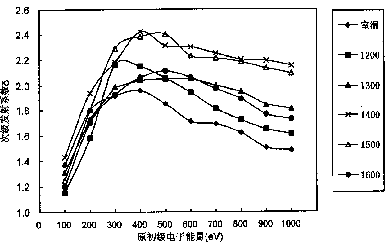
[0015] Example 3, 6.64 grams of lanthanum nitrate and 22.14 grams of yttrium nitrate were dissolved in water respectively, and added to 106.68 grams of powdered MoO 2 in (where La 2 o 3 Accounting for 5% by weight of molybdenum, Y 2 o 3 The weight ratio of molybdenum is 15%), the doped MoO 2 The powder is kept at 500°C under hydrogen for 2 hours to decompose rare earth nitrates into rare earth oxides, and then doped MoO in a multi-stage hydrogen furnace at 800-1000°C 2 Powder reduced to doped La 2 o 3 and Y 2 o 3 The composite rare earth molybdenum powder is made into a rare earth molybdenum rod with a certain size after pressing and sintering. After machining, a rare earth molybdenum sheet of φ10×1mm is made. Then laser welding is used to weld the rare earth aluminum sheet with the molybdenum cylinder and the metal tungsten wire used for heating, and after exhausting and activation treatment, the rare earth molybdenum experimental magnetron is made. The secondary em...
PUM
 Abstract
Description
Claims
Application Information