Vehicular hydrogen preparing method and device
A preparation device and hydrogen technology, applied in the direction of electric vehicles, electrical components, vehicle energy storage, etc., can solve the problems of scarcity of catalyst precious metals, potential safety hazards, unfavorable long-term storage, etc., and achieve low cost of hydrogen production, simple structure, and automation high effect
- Summary
- Abstract
- Description
- Claims
- Application Information
AI Technical Summary
Problems solved by technology
Method used
Image
Examples
Embodiment 1
[0034] Refer to attached Figure 6 , fuel cell hydrogen production method, adding 50g of NaBH with a purity of 97% in the reactor 4 Crystalline powder, the liquid feeding rod with a pore size of 5 μm made by the porous sintering process is used for quantitative small hole spraying method to add Co 2+ CoCl with a concentration of 0.14mol / L 2 The aqueous solution is sprayed with a 12V high-pressure pump, and the flow rate is 0.241 / h. Water cooling is used to control the reaction temperature within the range of 40-60° C., a total of 0.05 L of solution is added, and hydrogen gas is produced by reaction.
Embodiment 2
[0036] Refer to attached Figure 6 , fuel cell hydrogen production method, the 25g purity of 97% NaBH 4 with 25g of CaH with a purity of 97% 2 The powder is mixed evenly with the catalyst containing 8g of active material Co, and the carrier of the catalyst is Al 2 o 3 , into the reactor. Water is fed into the reactor feeding rod using a 12V high-pressure pump. The aperture of the feeding rod is 50 μm, and the flow rate of quantitative small hole injection is controlled at 0.3 l / h. The reaction temperature was controlled at 50-70° C., 0.05 L of the solution was added, and hydrogen gas was produced by reaction.
Embodiment 3
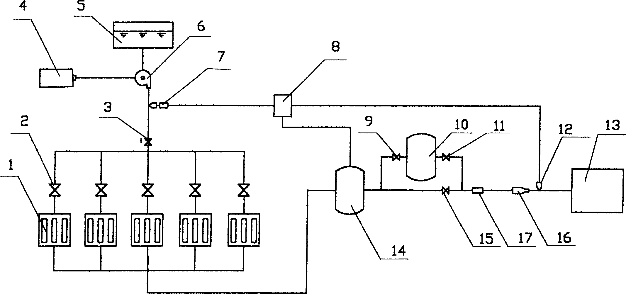
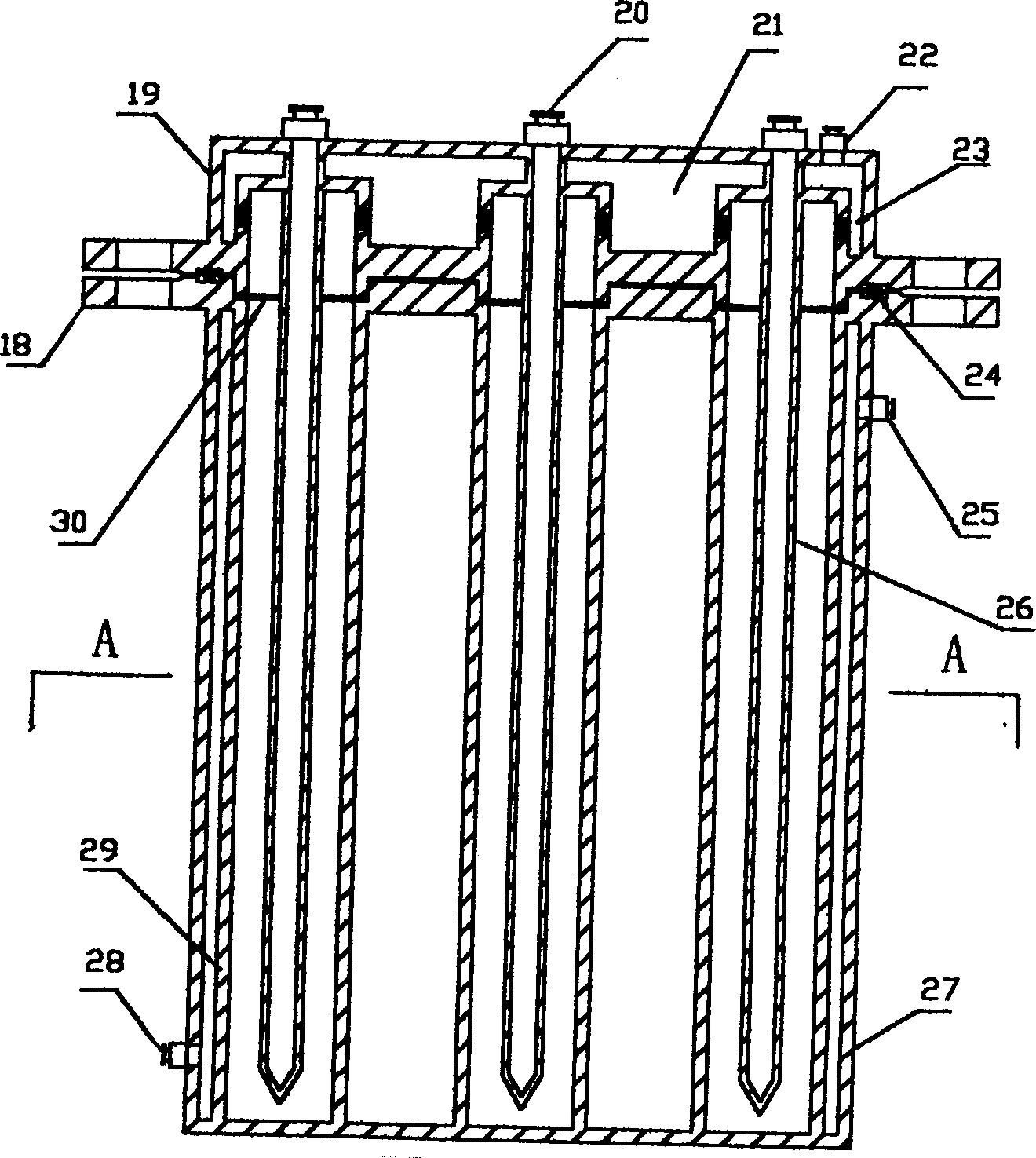
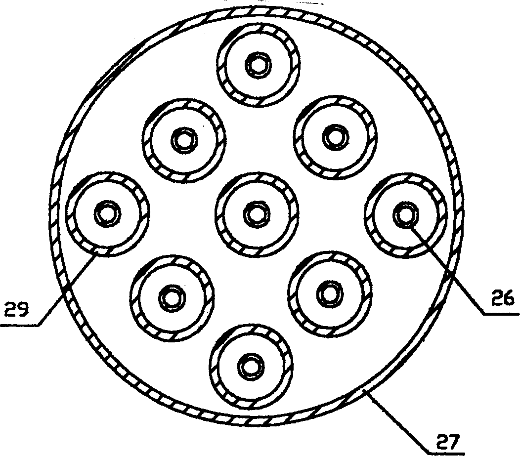
[0038] Refer to attached figure 1 , 2 , 3, 4, 5. The hydrogen preparation device for fuel cell vehicles is composed of a reaction device, a control device and a purification device. The connection structure and method are as follows: reactor 1 is 5 groups, through liquid pipelines, solenoid valve 2, check valve 3, cumulative flow measuring instrument 7. The 12V high-pressure pump 6 is connected to the liquid storage tank 5, and the storage battery 4 is the power source for starting the preparation device. The reactor 1 is connected with a buffer tank 14 , a pressure reducing valve 16 , an instantaneous flow measuring instrument 12 and a hydrogen utilization device 13 . The buffer tank 10 , the inlet electromagnetic valve 9 and the outlet electromagnetic valve 11 are arranged side by side with the electromagnetic valve 15 after the buffer tank 14 , and are connected with the membrane separation hydrogen purifier 17 after being merged. The buffer tank 14 is equipped with a pr...
PUM
 Abstract
Description
Claims
Application Information
 - R&D
- Intellectual Property
- Life Sciences
- Materials
- Tech Scout
- Unparalleled Data Quality
- Higher Quality Content
- 60% Fewer Hallucinations
Browse by: Latest US Patents, China's latest patents, Technical Efficacy Thesaurus, Application Domain, Technology Topic, Popular Technical Reports.
© 2025 PatSnap. All rights reserved.Legal|Privacy policy|Modern Slavery Act Transparency Statement|Sitemap|About US| Contact US: help@patsnap.com


