Variable-gain single-ended-to-difference radio-frequency low-noise amplifier

A low-noise amplifier and variable gain technology, which is applied in the field of RF low-noise amplifier structure design, can solve problems such as low-noise amplifier difficulties, circuit noise performance degradation, and increase, so as to reduce the number of active devices, eliminate insertion loss, and reduce system noise. Reduced effect

Inactive Publication Date: 2003-02-05
TSINGHUA UNIV
View PDF0 Cites 29 Cited by
  • Summary
  • Abstract
  • Description
  • Claims
  • Application Information

AI Technical Summary

Problems solved by technology

However, the fully differential structure also brings some disadvantages that cannot be overcome by itself: first, due to the fully differential structure, the DC bias current required by the circuit is twice that of the non-differential circuit, so that the power consumption of the circuit is also non-differential circuit This is contrary to the low-power design requirements of portable electronic equipment; second, due to the use of a fully differential structure, the number of active devices in the circuit increases, and the noise of the circuit also increases, so the circuit's The noise performance is degraded; thirdly, and most importantly, because the radio frequency signal from the antenna is a single-ended signal, therefore, the radio frequency signal must pass through a single-ended to differential balance converter B1 (balun) before passing through the low-noise amplifier, which will The single-ended signal from the antenna is converted into a differential signal and then passed through the low-noise amplifier, and this balun has a certain loss for the input RF signal, generally about 1dB, because this loss occurs before the input of the low-noise amplifier, so 1dB Loss means that the noise figure of the system increases by 1dB, and the noise figure of the low-noise amplifier is generally required to be less than 3dB. Therefore, if there is a loss of balun, the noise figure of the low-noise amplifier is required to be less than 2dB, and this requirement is for CMOS technology. Too difficult for low noise amplifiers
[0006] In addition, if a traditional low-noise amplifier wants to add a variable gain function, the following two methods are generally adopted: one is to change the transconductance of the MOS transistor (such as M1, M2) by adjusting the bias voltage of the MOS transistor, thereby Change the gain of the amplifier, but the bias adjustment circuit introduced by this method has a great influence on the matching of the input impedance, and the adjustment range of this method is very small; the other is to adjust the gain of the amplifier by adjusting the size of the output load , but the output load regulation circuit introduced by this method will also have a great impact on the output impedance matching of the signal
Therefore, these two methods will cause the circuit to obtain variable gain while the noise performance of the circuit will drop too much due to the problem of input and output impedance matching.

Method used


Image

  • Variable-gain single-ended-to-difference radio-frequency low-noise amplifier
  • Variable-gain single-ended-to-difference radio-frequency low-noise amplifier
  • Variable-gain single-ended-to-difference radio-frequency low-noise amplifier

Examples


Embodiment Construction

[0017] The single-ended to differential radio frequency low noise amplifier of variable gain that the present invention proposes is described in detail as follows in conjunction with accompanying drawing and embodiment:

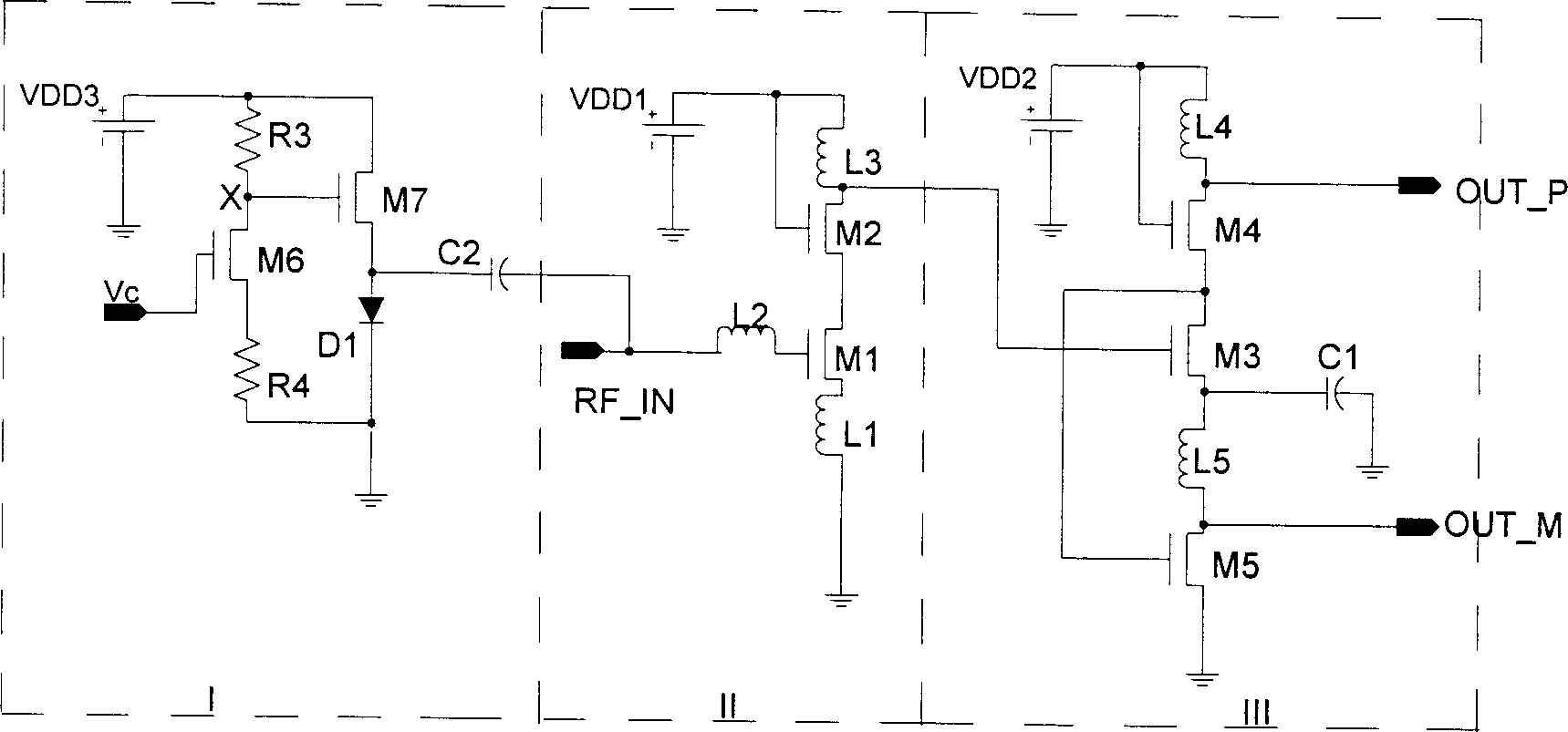
[0018] The radio frequency amplifier that the present invention proposes comprises three parts: main amplifier circuit (Main Amplifier Stage), as figure 2 Shown in the dashed box II; single-ended to differential output buffer (Single-to-Differential Output Buffer), such as figure 2 Shown in the dotted line box III; the variable gain unit (VGA Cell), such as figure 2 Shown in each dotted line box I; The specific circuit structure and connection relationship of each part are described in detail as follows:

[0019] The main amplifier circuit is mainly composed of MOS transistors M1 and M2, inductors L1, L2 and L3, and its connection relationship is: the radio frequency signal RF-IN is input to the gate of M1 through the inductor L2, the source of M1 is grou...


PUM


Abstract

The invention relates to the radio frequency low noise amplifier from the single end to the difference mode with variable gain belonging to the area of receiver technique in the wireless communication. The amplifier includes main amplifier circuit with single input end, the output buffer from the single end to the difference mode, which is connected to the outupt and input ends respectively, and the variable gain unit. The main amplifier consists of the 2 MOS tubes, 3 inductors. The buffer is composed of 3 MOS tubes, 2 inductors and 1 capacitor. The variable gain unit consists of 2 MOS tubes,2 resistors, capacitors and diodes. The invention provides the advantages of lowering the power consumption, improving the noise, removing the noise induced by the balum, controlling the gain as wellas lowering the requirement of the dynamic range for next stage.

Description

technical field [0001] The invention belongs to the technical field of wireless communication receiver systems, and in particular relates to the structure design of a radio frequency low noise amplifier used for the front end of the wireless communication receiver system. Background technique [0002] In the past ten years, the development and research of radio frequency integrated circuits (RFICs) have developed rapidly, which is mainly due to the prosperity of the wireless communication market. These wireless applications include pagers, cordless phones, radio frequency identification (RFID), analog and digital cellular mobile phones, and the Global Positioning System (GPS). At the same time, with the popularity of the Internet at an astonishing speed all over the world, some emerging short-distance, high-speed wireless communication systems—Wireless Local Area Network (WLAN) have also begun to develop rapidly in the past two years, mainly including IEEE802.11 series, Hype...

Claims


Application Information

Patent Timeline
Patent Type & Authority Applications(China)
IPC IPC(8): H03F1/26
CPCY02B60/50
Inventor 李永明陈弘毅林毅
Owner TSINGHUA UNIV
Why Eureka
Try Eureka