
Composite material producing extruding-casting, permeating and sintering process and equipment

A composite material and extrusion casting technology, which is applied in the direction of mechanical equipment, heat exchange equipment, rotors, etc., can solve the problem of not yet producing high melting point black metal-based particle-reinforced composite materials, and not producing high melting point black bimetallic composite materials, etc. Problems, to achieve the effect of small grain size, high utilization rate of metal materials, and smooth surface

Inactive Publication Date: 2003-04-09
丁刚
View PDF0 Cites 17 Cited by
  • Summary
  • Abstract
  • Description
  • Claims
  • Application Information

AI Technical Summary

Problems solved by technology

[0002] China "Casting" magazine, Vol. 51, No. 4, Page 205-208, April 2002, disclosed and reported the production of non-ferrous metals with low melting point by die casting in the article "Research Status and Prospects of Casting Metal-based Particle Reinforced Composite Materials". For metal-based particle-reinforced composite materials, no high-melting-point black metal-based particle-reinforced composite materials have been produced by the above method, nor have high-melting point black bimetallic composite materials and bimetallic composite materials containing hard phase reinforcement or self-lubricating Composites of materials

Method used


Image

  • Composite material producing extruding-casting, permeating and sintering process and equipment
  • Composite material producing extruding-casting, permeating and sintering process and equipment
  • Composite material producing extruding-casting, permeating and sintering process and equipment

Examples


Embodiment 1

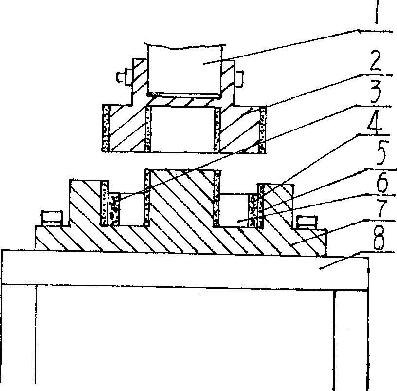
[0027] Example 1: figure 1 Among them, the equipment has a base 8, the base 8 is connected with a lower die 7, the lower die 7 is a lower die 7 with a core, an extrusion head 1 is arranged above the lower die 7, and the extrusion head 1 is connected to There is an upper die 2, the upper die 2 is a hollow upper die, the upper die 2 and the lower die 7 are coated with a heat-resistant coating 5, and a reinforced phase prefabricated block 4 is placed on the periphery of the lower die 2. The molten steel 6 is cast between the core of 7 and the reinforced phase prefabricated block 4, and the upper die 2 is pressed down to obtain a composite material.

[0028] First, according to the performance and working conditions of the product, select one or several refractory compound particles, or reinforcement phase materials such as short fiber whiskers, or alloy elements that can form carbides and a certain proportion of carbon. Proportion according to chemical dosage and add correspondi...

Embodiment 2

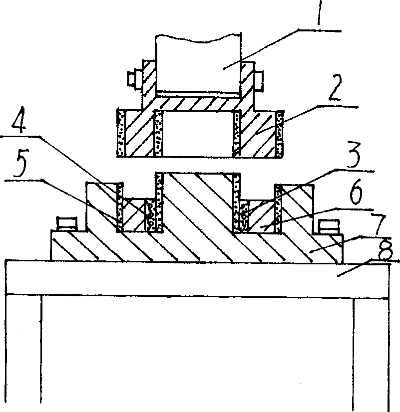
[0030] Example 2: figure 2 Among them, a reinforced phase prefabricated block 4 is placed in the center of the lower die 7, and molten steel 6 is cast between the core of the lower die 7 and the reinforced phase prefabricated block 4 to make a composite material with a reinforced phase material in the inner diameter. Others are the same as embodiment 1, omitted.

Embodiment 3

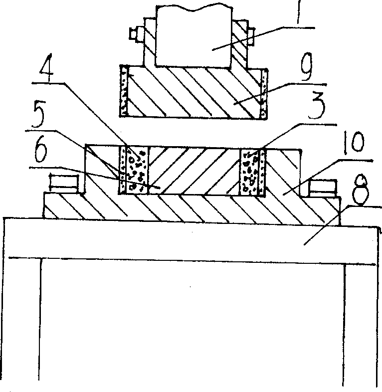
[0031] Example 3: image 3 Among them, the upper die 9 is a solid core die, the lower die 10 is a concave die, and the reinforced phase prefabricated block 4 is placed outside the inner cavity of the lower die 10, and the molten steel 6 is cast in the reinforced phase prefabricated block 4 to obtain Composite materials containing reinforcing phase materials or self-lubricating materials or mixtures thereof in the outer layer. Others are the same as embodiment 1, omitted.


PUM


Abstract

The technological process of producing composite material includes mixing reinforcing hard phase material, self-lubricating material and self-smelting alloy powder as well as adhesive and flux in certain proportion in a material mixer; pressing into prefabricated block in required shape and setting into stove after natural drying for 24 hr; preheating extruding and casting mold, painting heat resisting paint and stoving; setting the prefabricated block into the mold, stoving and casting with the refined molten metal; and extruding in a extruder to penetrate the molten metal into the interval between reinforcing phase material to obtain the reinforced composite material product.

Description

technical field [0001] The invention relates to a production process of a metal-based composite material and a bimetallic composite material with reinforcing phase materials on the surface, in particular to an extrusion casting infiltration sintering process for producing composite materials and equipment. Background technique [0002] China "Casting" magazine, Vol. 51, No. 4, Page 205-208, April 2002, disclosed and reported the production of non-ferrous metals with low melting point by die casting in the article "Research Status and Prospects of Casting Metal-based Particle Reinforced Composite Materials". For metal-based particle-reinforced composite materials, no high-melting-point black metal-based particle-reinforced composite materials have been produced by the above method, nor have high-melting point black bimetallic composite materials and bimetallic composite materials containing hard phase reinforcement or self-lubricating Composites of material...

Claims


Application Information

Patent Timeline
IPC IPC(8): B22D17/00B22D18/02B22D19/00
Inventor 丁刚孙茂来尤显卿强颖怀
Owner 丁刚
Learn More