Method and device for biological tissue photoacoustic tomography

A photoacoustic tomography, biological tissue technology, applied in echo tomography, acoustic wave diagnosis, infrasound wave diagnosis and other directions, can solve the complex reflection, transmission and absorption of laser sound field, it is difficult to obtain the exact photoacoustic signal of each point, the amount of calculation large problems, to achieve the effect of good applicability, improved signal-to-noise ratio, and simple algorithm

Inactive Publication Date: 2003-08-06
SOUTH CHINA NORMAL UNIVERSITY
View PDF0 Cites 22 Cited by
  • Summary
  • Abstract
  • Description
  • Claims
  • Application Information

AI Technical Summary

Problems solved by technology

At present, when measuring with a detector, the acoustic sensor is basically placed on the end face of the sample to measure the photoacoustic signal transmitted from the sample; the signal obtained in this way is generally the signal generated by each sound point of the bulk acoustic field at the measurement point. Therefore, it is difficult to reconstruct the photoacoustic image in the measured body or judge the signal of the exact point inside it. It requires multi-point measurement and complex algorithm to process data, and the calculation amount is very large; and for the application of biological tissue, because it is A strong scatterer of light, the incident laser diverges quickly, and biological tissue is generally not an isotropic optical and acoustic body, so the sound field generated by the laser and the reflection, transmission and absorption of the sound field are very complicated, and it is difficult to obtain the The exact photoacoustic signal, so simplifying the measurement signal is one of the key issues for the application

Method used


Image

  • Method and device for biological tissue photoacoustic tomography
  • Method and device for biological tissue photoacoustic tomography
  • Method and device for biological tissue photoacoustic tomography

Examples


Embodiment

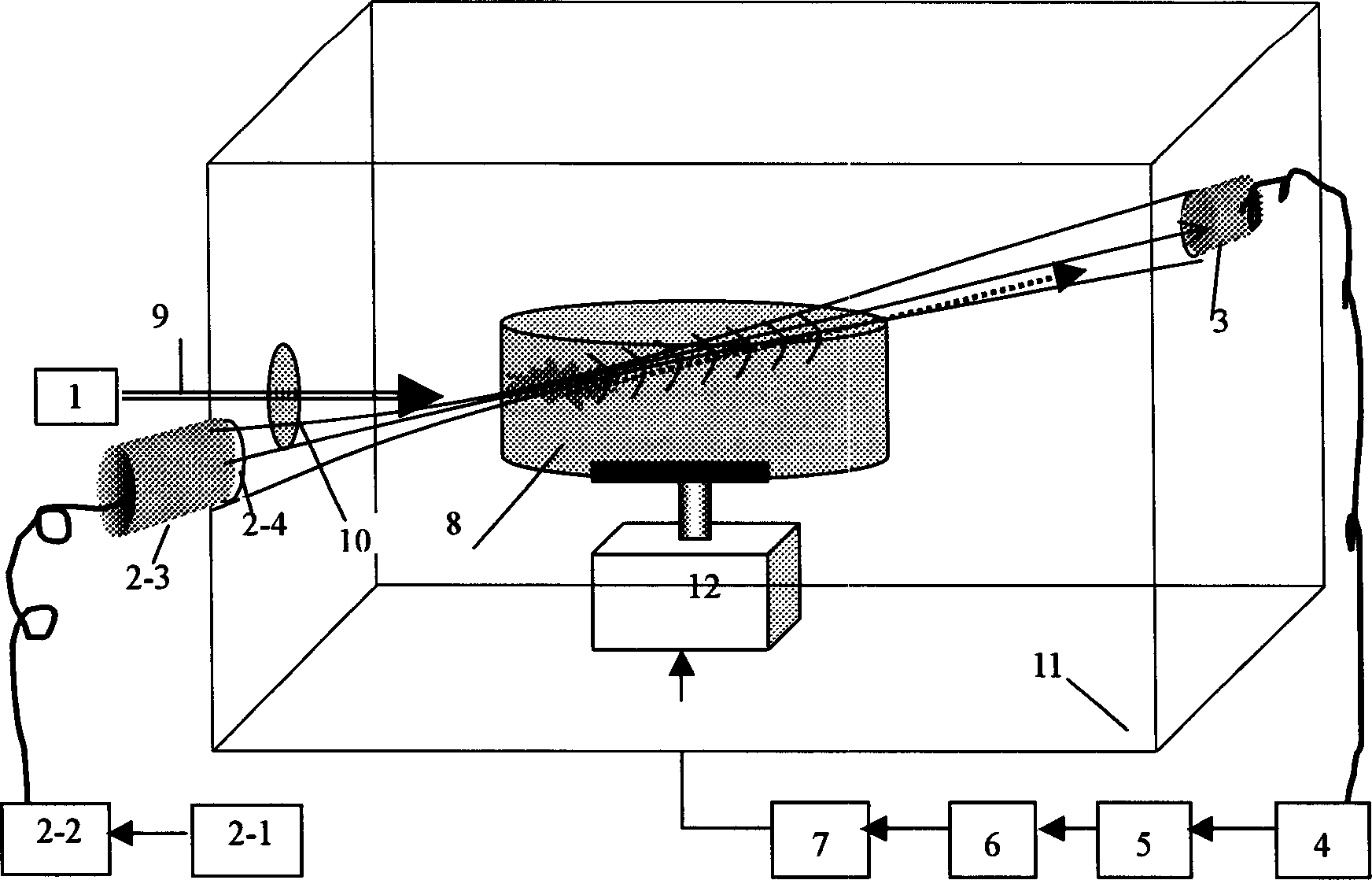
[0034] The specific structure of the present invention is as figure 1 shown by figure 1 It can be seen that the photoacoustic tomography device of the present invention is mainly composed of a laser 1, an ultrasonic generating component 2, an acoustic signal measuring component 3, a signal amplifier 4, a fast Fourier transform module 5, a data acquisition card 6, a computer 7, and a three-dimensional electric rotating platform 12 , the ultrasonic generation assembly 2 is relatively installed with the acoustic signal measurement assembly 3, and is connected through the ultrasonic signal, the acoustic signal measurement assembly 3, the signal amplifier 4, the Fourier transform module 5, the data acquisition card 6, the computer 7, etc. are electrically connected in turn; Component 2 is composed of a function generator 2-1, a power amplifier 2-2, an ultrasonic transducer 2-3 and an ultrasonic lens 2-4 connected in sequence, and the ultrasonic lens 2-4 is connected with the ultras...


PUM


Abstract

The biological tissue photoacoustic tomography method includes the following steps: (1). making pulse laser come into the biological tissue to produce photoacoustic signal; (2). making a beam of detection focus ultrasonic wave come into the photoacoustic zone, and interacting with photoacoustic signal to form superposition of the above-mentioned two signal; (3). receiving and measuring the superimposed signal; (4) making frequency spectrum separation by using computer, extracting and storing photoacoustic signal; and (5). making filtering and integration treatment of the photoacoustic signal,and utilizing the leaner projection algorithm to implement tissue chromatographic imaging. Said equipment includes laser, ultrasonic wave generator component, acoustic sgnal measuring component, signal amplifier, data collecting card, three-D electric rotating platform and computer.

Description

[0001] Technical field The present invention relates to photoacoustic tomography technology, in particular to a method and device for photoacoustic tomography in biological tissue. Background technique [0002] In recent years, research on the photoacoustic effect and photoacoustic tomography have received increasing attention. When a certain object is irradiated with light, its internal temperature will change due to its absorption of light, which will cause changes in the mechanical parameters of its local area; when a pulsed light source or modulated light source is used, the fluctuation of the local temperature inside the object will cause Its volume expands and contracts, thus radiating sound waves outward. This phenomenon is called photoacoustic field effect (referred to as photoacoustic effect). The photoacoustic effect is actually an energy conversion process. According to the heat conduction equation and wave equation,...

Claims


Application Information

Patent Timeline
Patent Type & Authority Applications(China)
IPC IPC(8): A61B6/00A61B8/00A61B8/13
Inventor 邢达曾亚光
Owner SOUTH CHINA NORMAL UNIVERSITY
Why Eureka
Try Eureka