

Multiple cutter blade and cutting tool
A tool and blade technology, applied in the field of cutting tools with multi-blade inserts, which can solve the problems of poor surface quality and poor chip evacuation performance
- Summary
- Abstract
- Description
- Claims
- Application Information
AI Technical Summary
Problems solved by technology
Method used
Image

Examples
Embodiment Construction
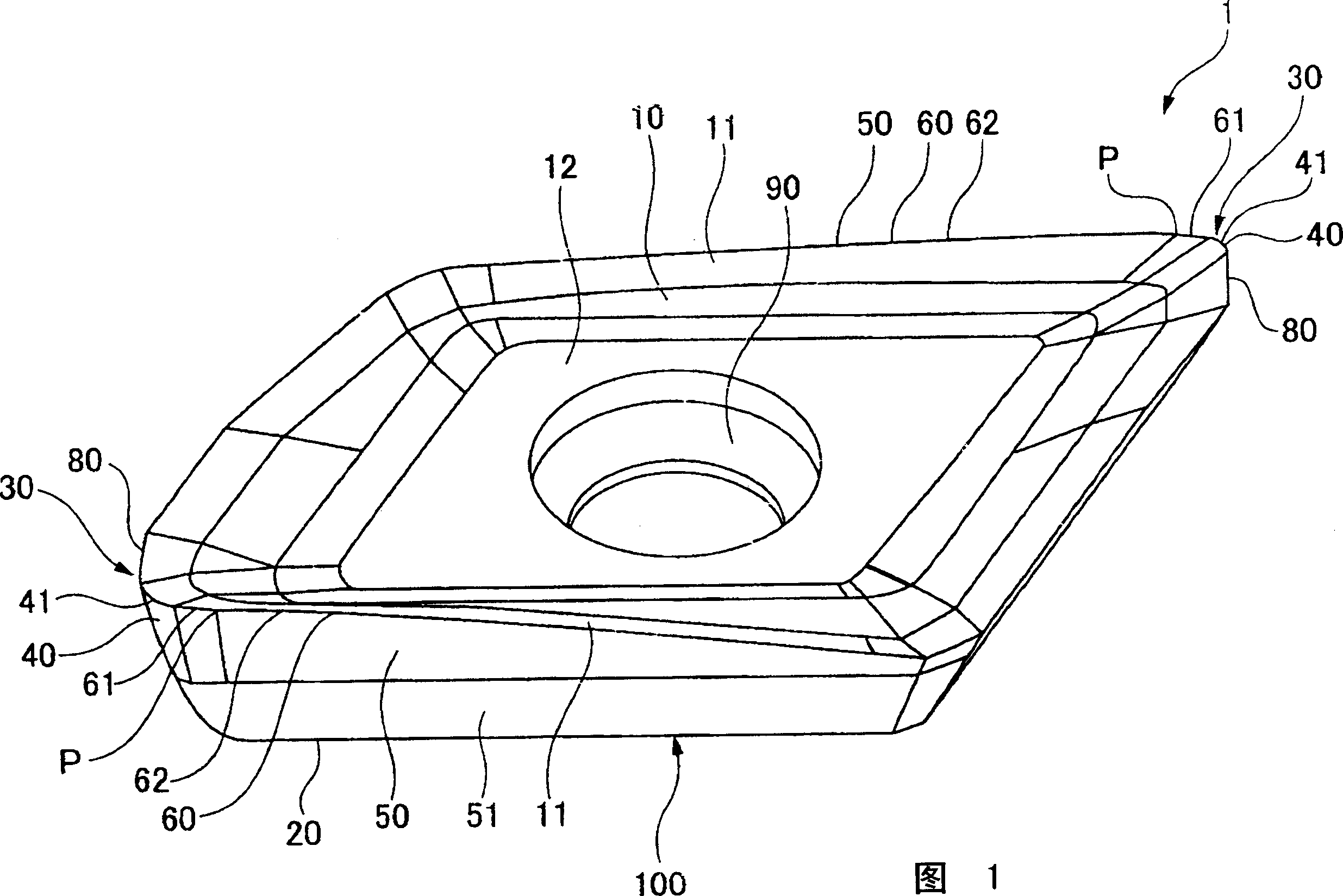
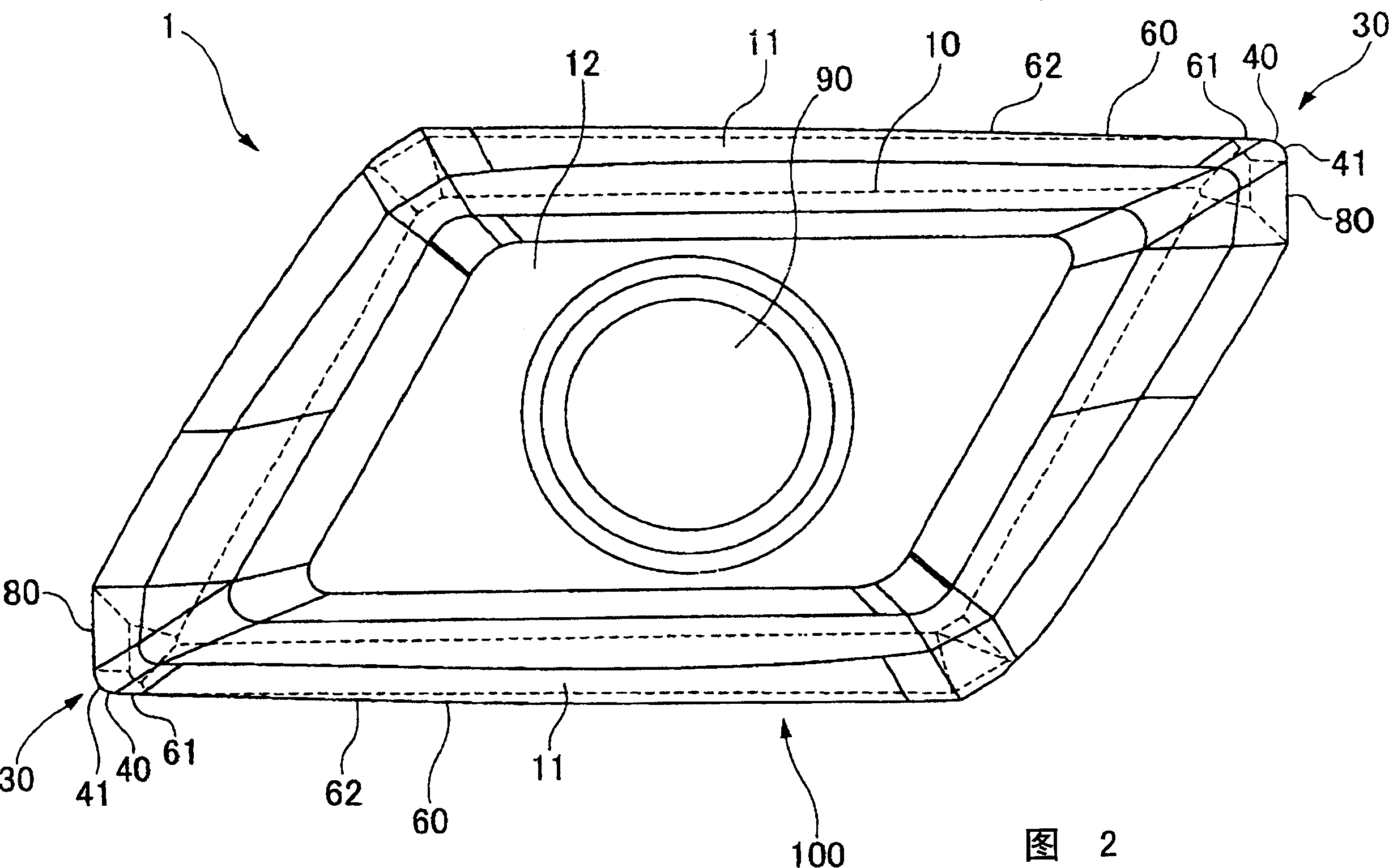
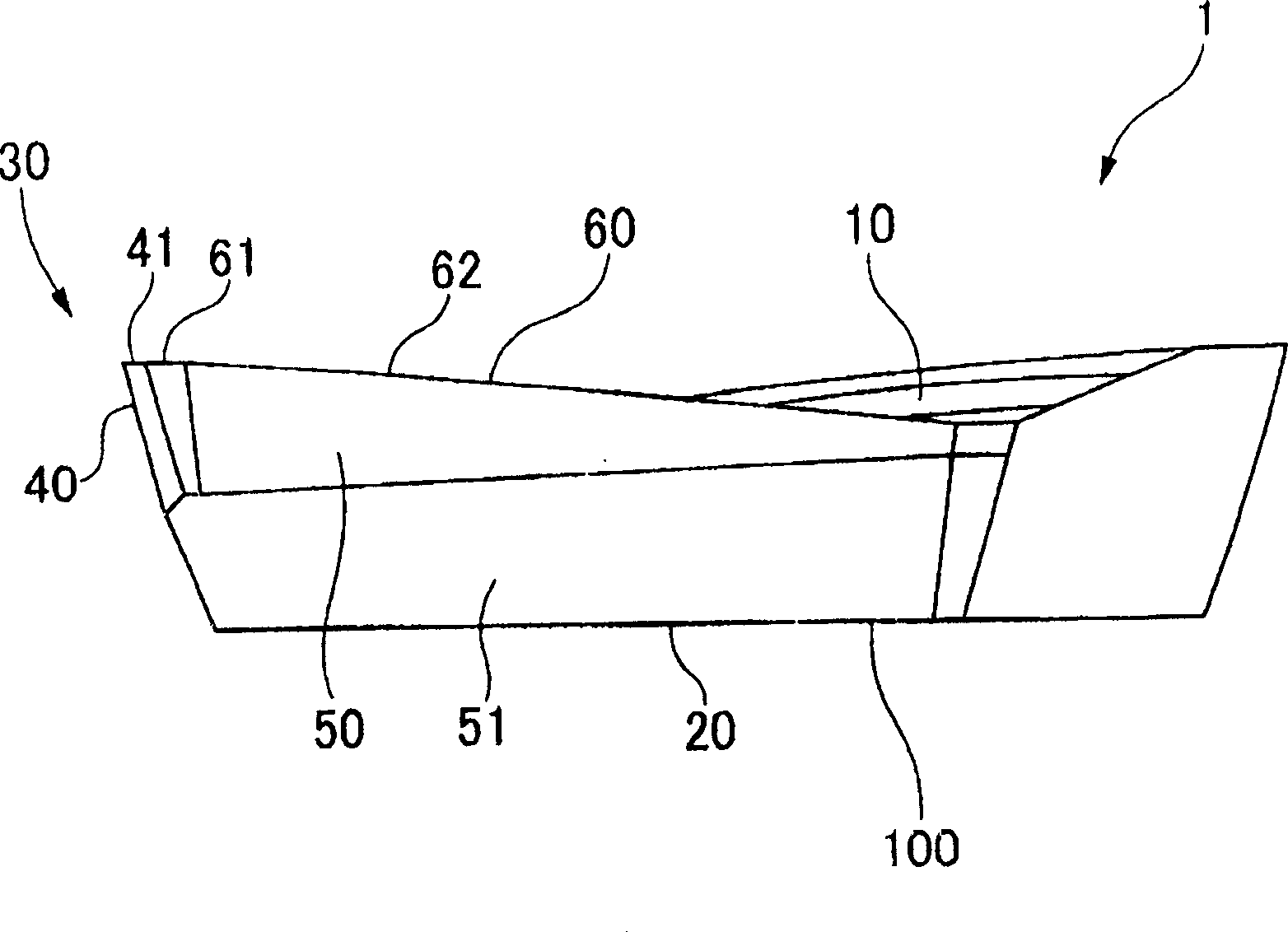
[0066] The multi-edged insert according to the present invention will be described below based on the drawings.
[0067] Figure 1~ Figure 4 The shown multi-edged insert 1 is, for example, made of cemented carbide or the like, and has a substantially polygonal plate shape, particularly a substantially quadrangular plate shape. The upper surface facing the thickness direction of the head main body 100 is used as the rake surface 10, and the lower surface is used as the tool body 200 such as an end mill (refer to Figure 5 ) on the mounting surface for installation.
[0068] Corner portions 40 , 40 are formed on the corner portions 30 , 30 facing each other in the diagonal direction of the parallelogram of the rake surface 10 . Cutting edges 41 , 41 having substantially arcuate shapes are formed on the intersecting ridges between the cutting edge portions 40 , 40 and the rake face 10 . In addition, the multi-edged insert 1 is formed so that the apex angle of the corner portio...
PUM
 Abstract
Description
Claims
Application Information