
Semiconducotr laser device and manufacturing method thereof

A technology of laser device and manufacturing method, which is applied in the direction of semiconductor laser device, semiconductor laser device, laser device, etc., and can solve problems such as aberration, excessively large interval of light-emitting points of laser beams, and increased number of parts and components

Inactive Publication Date: 2004-07-07
PIONEER CORP
View PDF1 Cites 2 Cited by
  • Summary
  • Abstract
  • Description
  • Claims
  • Application Information

AI Technical Summary

Problems solved by technology

[0014] However, in the above-mentioned structure, as described in the above-mentioned patent document, since the first substrate (GaN substrate) usually has a thickness of about 100 μm, as a result, there is a problem that the laser beam emission position of the GaN-based laser oscillator part (The position of the luminous point) and the laser beam emission position (the position of the luminous point) of the AlGaInP-based laser oscillator and the AlGaAs-based laser oscillator are too large, that is, the distance between the luminous points of each laser beam is too large. question
[0015] For example, when recording or reproducing after mounting the above-mentioned semiconductor laser device on an optical pickup, the emission position (the position of the light-emitting point) of the GaN-based laser oscillation part is performed on the basis of the optical axis of the optical system constituting the optical pickup. When the optical axes are aligned, the emission positions (positions of light-emitting points) of the AlGaInP-based laser oscillator and the AlGaAs-based laser oscillator are largely deviated from the center of the optical axis of the optical system due to the influence of the thickness of the first substrate. Aberration etc.
[0016] In addition, if the laser beam emitted from the GaN-based laser oscillator and the laser beams emitted from the AlGaInP-based laser oscillator and the AlGaAs-based laser oscillator are both located on the optical axis of the optical system of the optical pickup, it is necessary to install a prism, etc. Optical elements to eliminate the adverse effect caused by the thickness of the first substrate, so there is a problem that the number of parts increases

Method used


Image

  • Semiconducotr laser device and manufacturing method thereof
  • Semiconducotr laser device and manufacturing method thereof
  • Semiconducotr laser device and manufacturing method thereof

Examples


no. 1 Embodiment

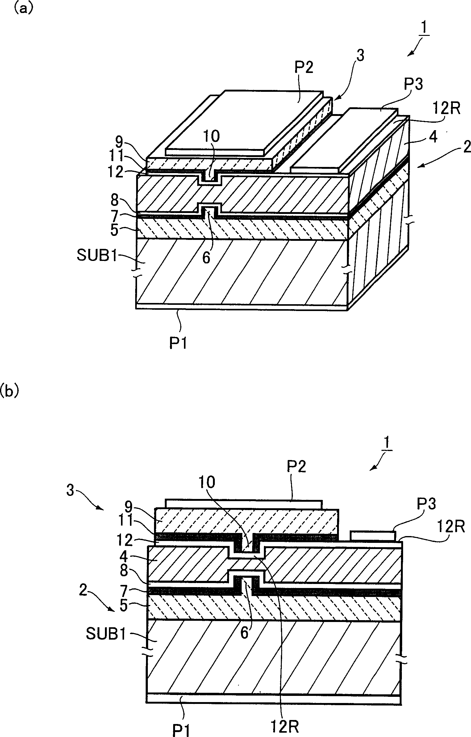
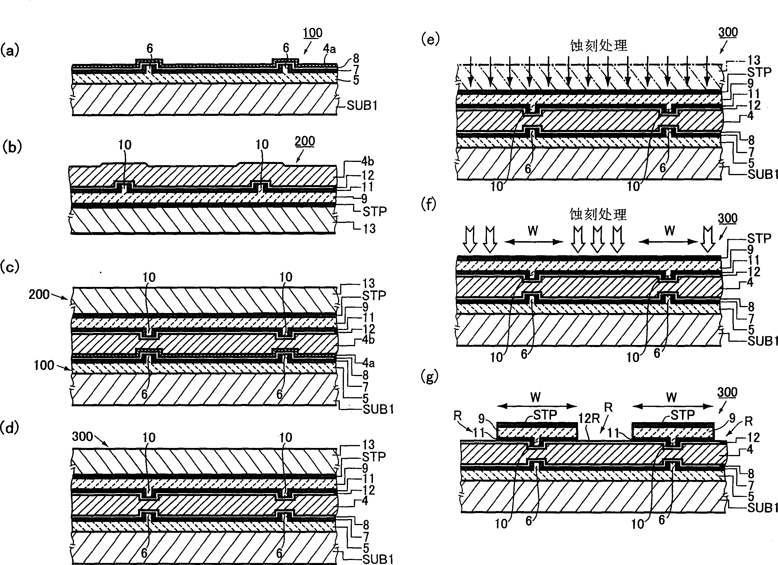
[0085] Below, refer to Figure 5 to Figure 7 A more specific example of the first embodiment will be described.

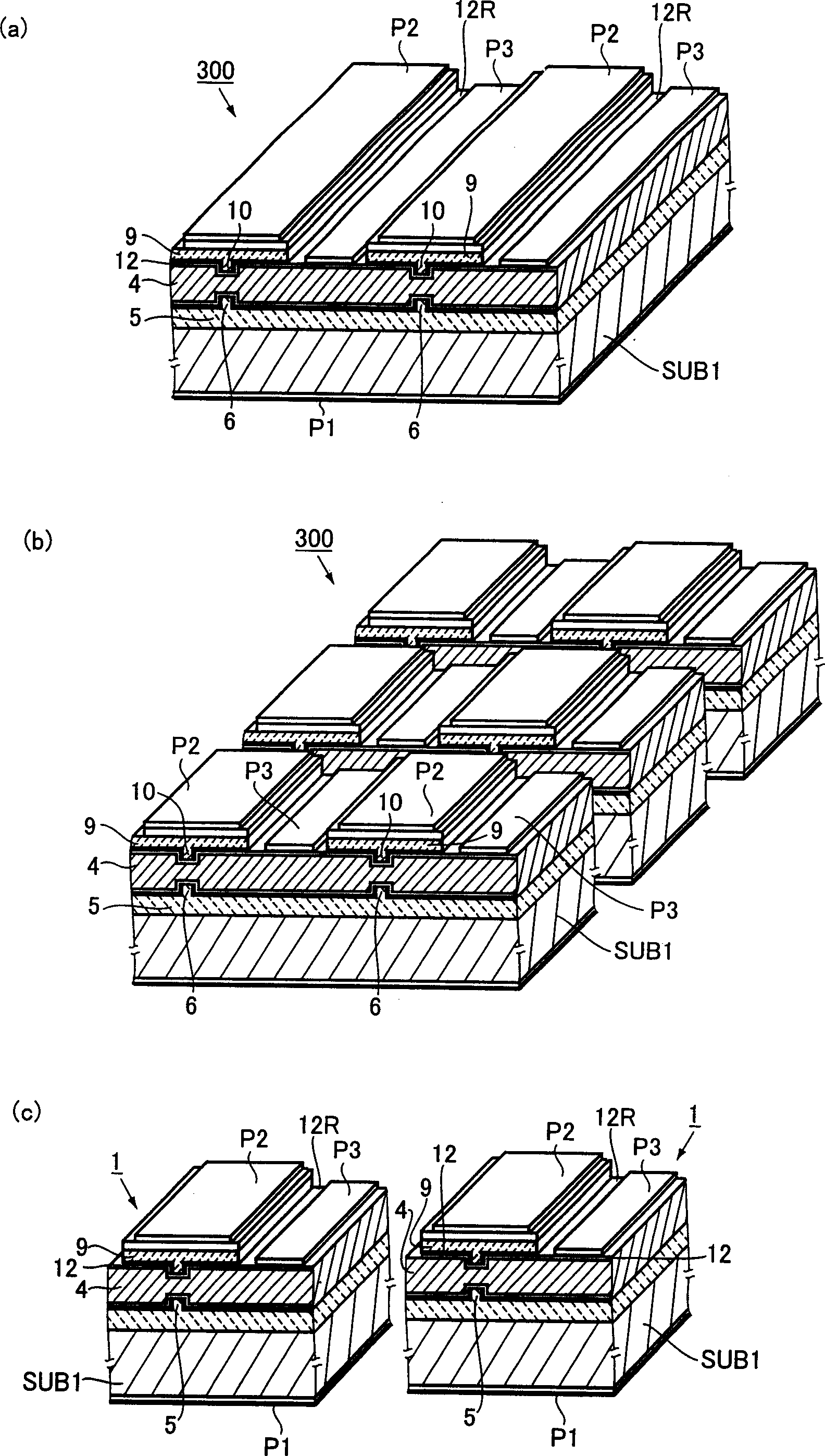
[0086] Figure 5 is corresponding to figure 1 (a) and figure 1 (b) is a longitudinal sectional view showing the structure of the semiconductor laser device of this embodiment. Image 6 and Figure 7 The manufacturing process of this semiconductor laser device is shown. However, in Figure 5 to Figure 7 in, with Figure 1 to Figure 3 The same or equivalent parts will be denoted by the same symbols.

[0087] Such as Figure 5 As shown, the semiconductor laser device 1 of this embodiment has a hybrid structure in which the first light-emitting element 2 belonging to the GaN-based laser (blue laser) and the second light-emitting element 3 belonging to the AlGaInP-based laser (red laser) are provided with The conductive welded metal layer 4 is bonded integrally.

[0088] The first light-emitting element 2 includes a laser oscillating portion 5 formed on a semi...

no. 2 Embodiment

[0135] Below, refer to Figure 8 A second example of the first embodiment of the present invention will be described. However, Figure 8 is a longitudinal sectional view showing the structure of the semiconductor laser device of this embodiment, wherein, and figure 1 (b) The same or equivalent parts will be denoted by the same symbols.

[0136] Such as Figure 8 As shown, the present semiconductor laser device has a configuration as described below. which is, figure 1 The semiconductor laser device 1 shown in (b) is bonded to a support substrate (auxiliary carrier) 1000 such as ceramics having high thermal conductivity and electrical insulation.

[0137] Patterned electrode layers P11 and P31 made of metal such as Cu are formed on the surface of the support substrate 1000 by vapor deposition or the like. The laser oscillating part 9 of the second light emitting element 3 is fixed on the electrode layer P11 through the extremely thin welding metal layer AP, and the ohmic ...


PUM


Abstract

An improved semiconductor laser device is provided which has a small distance between laser light emitting spots. Such laser device comprises i) a first light emitting element (2) including a laser oscillation section (5) provided with a ridge waveguide (6) and formed by forming a group III nitride semiconductor film on a substrate (SUB1), an insulating layer (7) and an ohmic electrode layer (8), ii) a second light emitting element (3) including a laser oscillation section (9) provided with a waveguide (10) and formed by forming III-V compound semiconductor film, an insulating layer (11) and an ohmic electrode layer (12). By virtue of the adhesive metal layer interposed between the two ohmic electrode layers (8,12), the two laser oscillation sections (5,9) are combined together, thereby forming the improved semiconductor laser device (1)which has a small distance between laser light emitting spots of the two laser oscillation sections (5,9).

Description

technical field [0001] The present invention relates to a semiconductor laser device capable of emitting a plurality of laser beams with different wavelengths and a manufacturing method thereof. Background technique [0002] In recent years, a semiconductor laser device called a multi-wavelength laser capable of emitting a plurality of laser beams having different wavelengths has been continuously researched and developed. [0003] In the field of information recording and reproducing devices for recording or reproducing information on storage media represented by CD (Compact Disc) and DVD (Digital Versatile Disc), etc., in order to develop optical pickups that are suitable for various storage media It is important to develop a semiconductor laser device capable of emitting a plurality of laser beams with different wavelengths. [0004] As such a semiconductor laser device, a hybrid structure has been proposed in order to eliminate the difficulty encountered when using a si...

Claims


Application Information

Patent Timeline
Patent Type & Authority Applications(China)
IPC IPC(8): H01S5/22H01S5/02H01S5/042H01S5/323H01S5/327H01S5/343H01S5/40
CPCH01S5/0425H01S5/02272H01S5/22H01S5/0202H01S5/4087H01S5/4043H01S5/0217H01S5/0224H01S5/32341H01L2224/48463H01S5/04256H01S5/0234H01S5/0237
Inventor 宫地护渡边温高桥宏和木村义则
Owner PIONEER CORP
Learn More