
Coil circuit board and surface mounted type coil element

A surface mount type, coil component technology, applied in coil manufacturing, electrical components, transformer/inductor coil/winding/connection, etc., can solve the difficulty of removing resist and base conductor layer, increase of DC resistance, pattern peeling And other issues

Active Publication Date: 2005-02-02
TDK CORPARATION
View PDF6 Cites 25 Cited by
  • Summary
  • Abstract
  • Description
  • Claims
  • Application Information

AI Technical Summary

Problems solved by technology

[0013] That is, the base conductor layer (seed layer) pattern is first formed, and then the resist and the base conductor layer are removed by etching to form a mushroom-shaped cross-sectional pattern. However, regardless of the aspect ratio of the gap in the conductor portion , when the width is 20 μm or less, the removal of the resist and the base conductor layer becomes difficult
In addition, when the base conductor layer is etched, the circuit line becomes thinner and the root of the circuit line becomes thinner, which causes problems such as increased DC resistance and peeling of the pattern from the substrate due to a decrease in adhesion strength.

Method used


Image

  • Coil circuit board and surface mounted type coil element
  • Coil circuit board and surface mounted type coil element
  • Coil circuit board and surface mounted type coil element

Examples


Embodiment

[0067] In the following, the coil circuit board and the surface-mounted coil component according to the present invention will be described in detail.

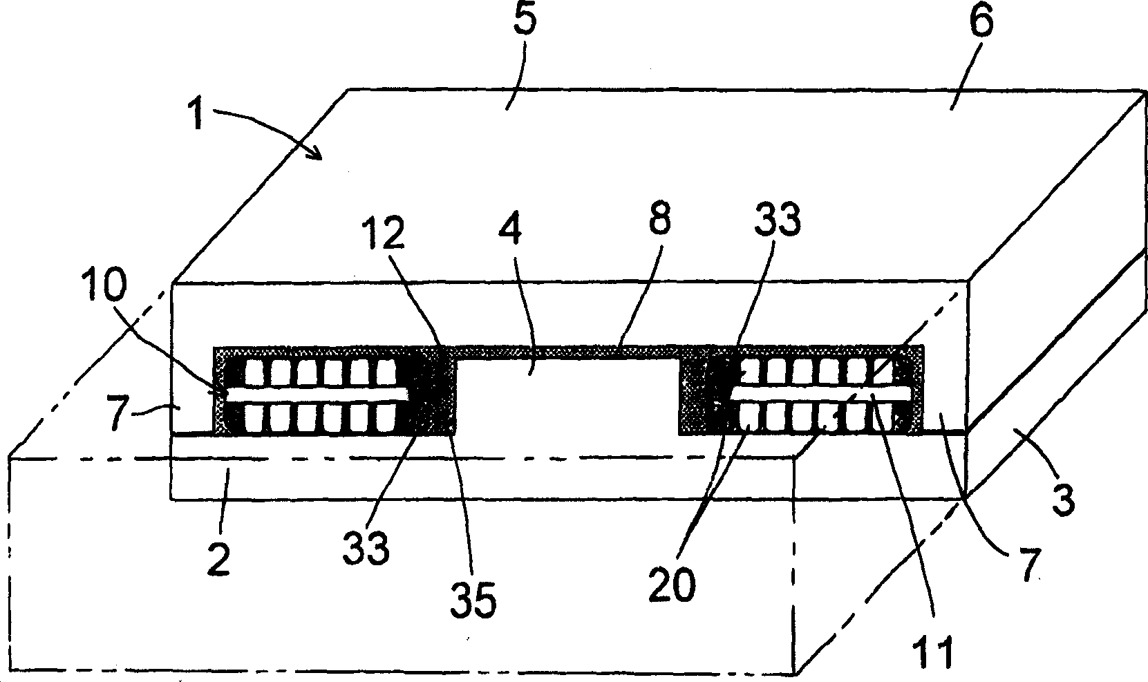
[0068] For a glass fiber cloth plate (a plate made of glass fiber cloth impregnated with BT resin) with a thickness of 60 μm and a connection hole and a through hole for the insertion of the central convex part, the upper and lower surfaces are formed by electroless plating with a thickness of 0.1 to 10 μm. A Cu film of 1 μm was used as the base conductor layer. Secondly, form a photosensitive electrodeposited resist film and use photolithography to form a spiral pattern that will become a coil conductor on both sides of the glass fiber cloth, with a voltage of not more than 15A / dm 2 Electroplating was carried out for about 20 minutes at a high current to form a Cu conductor pattern with a height of 35 μm and a width of 35 μm. After peeling off the resist mask for selective plating, the base conductor layer was etched, and a ...


PUM

PropertyMeasurementUnit
Dc resistanceaaaaaaaaaa

Abstract

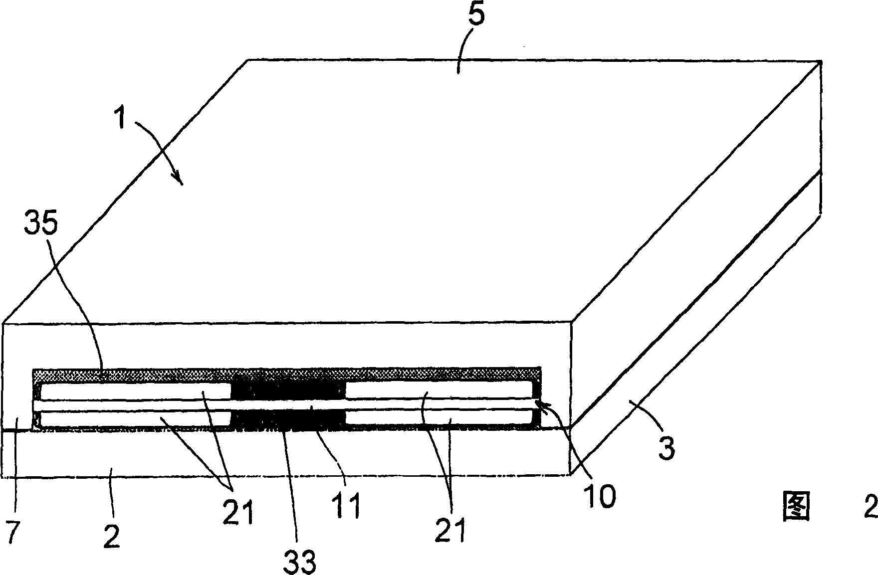
Provided is a coil substrate and a surface mounting type coil element which have higher inductance and low resistance coil conductor and are manufactured with less number of processes. Magnetic cores 2 and 5 are provided face to face. A spiral coil conductor 20 is formed to the front and rear surfaces of a core structure body 1 having an external core closed at both ends and a central leg, and of an insulating plate 11 including a through hole 12 at the center thereof. Moreover, a coil substrate 10 mutually connecting the spiral coil conductors 20 at the front and rear surfaces via the front and rear contacts and an external electrode connected to the coil conductor 20 are also provided. Under the condition that the central leg is inserted into the through-hole 12, the coil substrate 10 is allocated at the internal side of the core structure body 1 and the magnetic cores 2, 5 include a gap at the central leg.

Description

[0001] The technical field of the invention [0002] The present invention relates to coil (coil) circuit boards and surface mount type coil components widely used in electrical products such as civil equipment and industrial equipment. A coil circuit board and a surface-mounted coil component that can be manufactured with fewer steps and at a lower cost, and are particularly suitable for use in the frequency range of 10 kHz to 20 MHz. Background technique [0003] In the past, such surface mount coil components have been widely used in electrical products such as consumer equipment and industrial equipment. Among them, small portable devices need to obtain multiple voltages from a single power supply in order to drive various devices as their functions are enriched, and surface mount coil components are also used in such power supplies. To apply it to these small portable devices, it is necessary to meet the requirements in terms of electrical insulation performance and reli...

Claims


Application Information

Patent Timeline
IPC IPC(8): H01F17/00H01F17/04H01F27/28H01F41/04
CPCE02D5/223E02D5/28E02D27/12
Inventor 菊池俊秋赤川淳前田佳宏佐藤玲
Owner TDK CORPARATION
Learn More