Reflux type temperature controllable sludge drying device and method

A sludge drying and sludge technology, applied in the direction of dewatering/drying/concentrating sludge treatment, can solve the problems of large energy consumption, high operating costs, complex sludge composition, etc., and achieve obvious economic benefits.

Inactive Publication Date: 2005-03-02
ZHEJIANG UNIV
View PDF0 Cites 47 Cited by
  • Summary
  • Abstract
  • Description
  • Claims
  • Application Information

AI Technical Summary

Problems solved by technology

[0003] (1) Landfill, which not only requires sufficient space and necessary environmental protection means, but also transports, which makes the treatment cost higher, and it is impossible to find a space and place suitable for landfilling sludge around the city
[0004] (2) Incineration, sludge incineration equipment has high investment and energy consumption, which makes the operation cost expensive. The cost of sludge incineration treatment per ton is generally more than 400 yuan. According to the current situation in our country, sludge incineration treatment is economically economical. Unbearable
[0008] The rich organic matter contained in the sludge produced by the sewage treatment plant is the main part of the sludge that can be used as a resource. In order to keep most of the organic matter in the drying process without being damaged, the drying heat is provided. It should not be too high, but the moisture content of the sludge after pressure filtration is generally about 80%. If the heat provided during drying is not high enough, it will affect the efficiency of sludge drying; in addition, the sludge components produced in sewage treatment It is very complicated, and the sludge produced after different sewage treatment has great differences in physical and chemical properties
If traditional drying equipment and technology are used to dry sludge with complex components and great changes in physical and chemical properties, it will be impossible to meet the technical requirements.

Method used


Image

  • Reflux type temperature controllable sludge drying device and method
  • Reflux type temperature controllable sludge drying device and method
  • Reflux type temperature controllable sludge drying device and method

Examples


Embodiment Construction

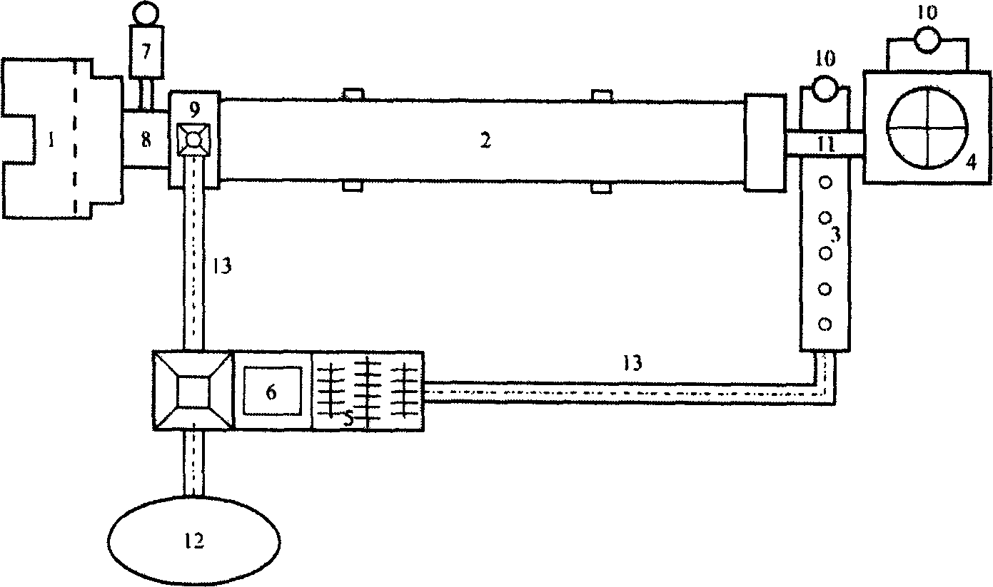
[0019] The return-type temperature-controllable sludge drying device has sequentially connected heating furnace 1, heat pipe 8, rotary kiln 2, cold air blowing off equipment 3, conveyor belt 13, pulverizer 5, material distribution screen 6, granulator 12, A jet air inducer 7 is provided on the side of the heat pipe 8, and the rotary kiln 2 and the cold air blowing off equipment 3 are connected to the dust removal and degassing equipment 4 through the ventilation pipe 11. The fan 10 and the top of the front end of the rotary kiln 2 are provided with a sludge inlet 9), and the material distribution screen 6 is connected with the sludge inlet 9 through a conveyor belt 13. See attached figure 1 .

[0020] In this device, the heat provided by the heating furnace can be generated by burning coal or by gas. The jet induced air device is used to control the heat provided for sludge drying, and the temperature during sludge drying is adjusted according to the properties of sludge and...


PUM

PropertyMeasurementUnit
particle diameteraaaaaaaaaa

Abstract

The present invention discloses one kind reflux type temperature controllable sludge drying apparatus and method. Drying sludge in 5-20 % is mixed with wet sludge and through the sludge inlet with two, one transverse and one longitudinal, layers of cutting steel wires, sludge is cut into small blocks before entering into the rotary kiln. Inside the rotary kiln, sludge is thrown and crushed by the throwing plate and chain for fast heating to dry in the temperature controlled with the jetting blower. Hot sludge from the rotary kiln is blown with the cold wind blower to further dry. The dried sludge is crushed and sieved, sludge with size below 4 mm is pelletized for comprehensive utilization and large sized sludge is refluxed. The present invention can reach ideal drying effect while maintaining over 95 % of its organic matter components.

Description

technical field [0001] The invention relates to a return type temperature-controllable sludge drying device and method. Background technique [0002] Industrial wastewater (including printing and dyeing, papermaking, leather, chemical and various mechanical industries) and domestic sewage after biochemical treatment, while the sewage is purified, will produce volume accounting for about 1% of the total sewage entering the sewage treatment plant In addition to concentrated inorganic and organic pollutants, this kind of sludge also contains a large number of pathogens and various heavy metal elements. Therefore, it is an important part of the sewage treatment system to safely and economically dispose of the sludge generated in sewage treatment. If the sludge is not properly treated, it will not only directly affect the normal operation of the sewage treatment system, but also give The environment brings secondary pollution. At present, the treatment of this kind of sludge at...

Claims


Application Information

Patent Timeline
Patent Type & Authority Applications(China)
IPC IPC(8): C02F11/12
Inventor 翁焕新
Owner ZHEJIANG UNIV
Why Eureka
Try Eureka