Super-short pulse laser with Yb dosed optical fiber

A technology of ytterbium-doped fiber and ultra-short pulse, which is applied in the laser field, can solve the problems of reduced stability and reliability of the laser system, loss of mode-locking of the laser, large grating loss, etc., to achieve light weight, avoid spectrum narrowing, and reliability increased effect

Inactive Publication Date: 2005-05-11
XI'AN INST OF OPTICS & FINE MECHANICS - CHINESE ACAD OF SCI
View PDF0 Cites 3 Cited by
  • Summary
  • Abstract
  • Description
  • Claims
  • Application Information

AI Technical Summary

Problems solved by technology

Photonic crystal fiber, chirped fiber grating in the cavity dispersion compensation technology is not yet mature, the grating pair is usually used for dispersion compensation in the cavity, because the loss introduced by the grating pair is large and the stability is poor
If a grating pair is introduced into the oscillator of the fiber laser to compensate for dispersion, the laser may lose its mode locking due to changes in the external environment, which greatly reduces the stability and reliability of the entire laser system

Method used


Image

  • Super-short pulse laser with Yb dosed optical fiber
  • Super-short pulse laser with Yb dosed optical fiber
  • Super-short pulse laser with Yb dosed optical fiber

Examples


Embodiment 1

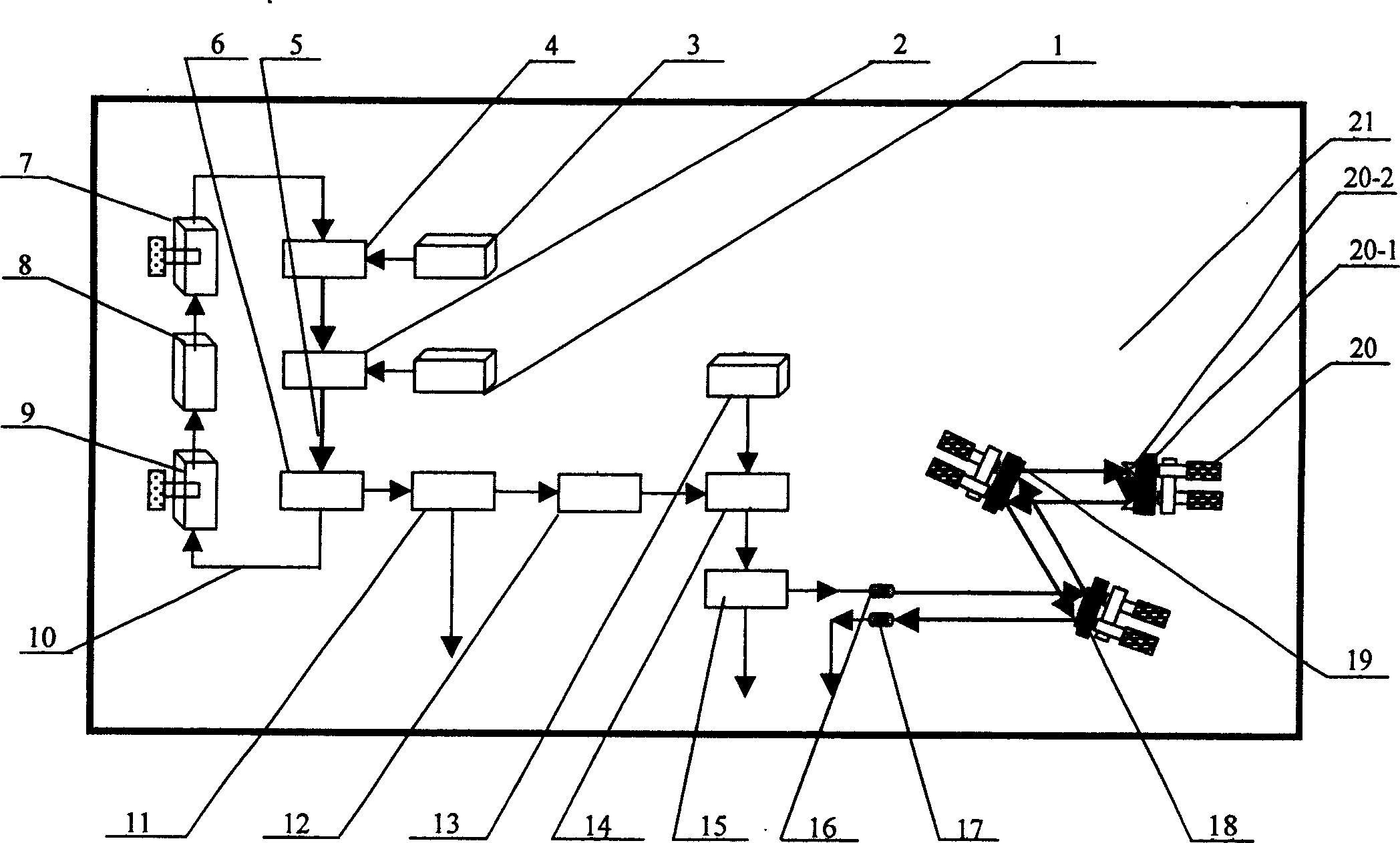
[0017] exist figure 1 Among them, the ytterbium-doped fiber ultrashort pulse laser in this embodiment is composed of an oscillator front-end pump source 1, an oscillator front-end wavelength division multiplexer 2, an oscillator back-end pump source 3, and an oscillator back-end wavelength division multiplexer. 4, ytterbium-doped fiber 5, oscillator output coupler 6, front-end polarization controller 7, polarization-related optical isolator 8, back-end polarization controller 9, ordinary undoped fiber 10, oscillator detection output coupler 11 , polarization-independent optical isolator 12, amplifier pump source 13, amplifier wavelength division multiplexer 14, amplifier detection output coupler 15, collimating coupling lens 16, converging coupling lens 17, diffraction grating 18, collimating grating 19 , a lifting mirror 20, and a mounting plate 21 are connected to form an oscillator, wherein the oscillator front-end pump source 1 to the oscillator detection output coupler 11...

Embodiment 2

[0025] In this embodiment, the total reflection film vacuum-evaporated on the slopes of the two rectangular prisms 20-2 is 3 layers of aluminum oxide coating. Other components and the coupling relationship of the components are the same as in Embodiment 1.

Embodiment 3

[0027] In this embodiment, the total reflection film vacuum-evaporated on the slopes of the two rectangular prisms 20-2 is five layers of aluminum oxide coating. Other components and the coupling relationship of the components are the same as in Embodiment 1.

[0028] The working principle of the present invention is as follows:

[0029] Add the pump power of the front-end pumping source 1 of the oscillator and the pumping source 3 at the back-end of the oscillator to the maximum value, and the pumping light of the pumping source 1 at the front-end of the oscillator passes through the ordinary undoped optical fiber 10 and passes through the front-end wavelength division of the oscillator. The multiplexer 2 enters the ytterbium-doped fiber 5 to generate continuous laser light, and the pump light of the pump source 3 at the back end of the oscillator passes through the ordinary undoped fiber 10, passes through the wavelength division multiplexer 4 at the back end of the oscillat...


PUM


Abstract

The polarization controller, wavelength division multiplexer in the back end of oscillator, pumping source in the back end of oscillator are set at first row in broad ways on the mounted panel. The optical isolator relating the polarization, wavelength division multiplexer at front end of oscillator, pumping source in front end of oscillator, pumping source of amplifier are set on the second row in broad ways on the mounted board. The back end polarization controller, osc out coupler, osc check and out coupler, optical isolator not relating to polarization, wavelength division multiplexer of amplifier, collimated grating, and lifting mirror are set at the third row in broad ways on mounted board. The check out and output coupler of amplifier, collimation coupling lens, and diffraction grating are set at the fourth row in broad ways on the mounted board. The convergence coupling les is set at fifth row in broad ways on mounted board.

Description

technical field [0001] The invention belongs to the field of laser technology, and in particular relates to an ytterbium-doped fiber ultrashort pulse laser. Background technique [0002] Due to its small size, light weight, high reliability, high light-to-light conversion efficiency, and good beam quality and many other characteristics, fiber lasers have been more and more widely used in various fields such as optical communications, medicine, and biology. Fiber lasers using ytterbium-doped silica fiber as the laser gain medium have developed rapidly in recent years, mainly due to the high absorption cross section of ytterbium ions, no excited state absorption, high conversion efficiency, wide gain bandwidth and easy generation of ultrashort Pulsed, Ytterbium-doped fiber lasers have very high gain, and their gain bandwidth supports transform-limited pulses of less than 30 fs. High-power ultrashort optical pulses are easily obtained by cladding pumping techniques. Using the...

Claims


Application Information

Patent Timeline
Patent Type & Authority Applications(China)
IPC IPC(8): H01S3/00H01S3/067
Inventor 陈国夫赵卫杨玲珍王屹山
Owner XI'AN INST OF OPTICS & FINE MECHANICS - CHINESE ACAD OF SCI
Why Eureka
Try Eureka