Signal transmitter

A transmitter, high-frequency technology, applied in transmission systems, power amplifiers, amplifiers, etc., can solve problems such as leakage power degradation, inability to achieve high efficiency, and achieve correct compensation of temperature characteristics, simple structure, and high efficiency. Effect

Inactive Publication Date: 2005-06-08
PANASONIC CORP
View PDF2 Cites 8 Cited by
  • Summary
  • Abstract
  • Description
  • Claims
  • Application Information

AI Technical Summary

Problems solved by technology

Due to the incompleteness of distortion compensation, the next-adjacent channel leakage power is further deteriorated, so it is not allowed in the EER method
[0016] Therefore, although it is necessary to reflect the output of the high-frequency power amplifier, high efficiency cannot be achieved when going through complicated processing and circuits like the second prior art, especially when improving the power efficiency of the transmitter like the EER method For the purpose, the improvement effect of the EER method offsets each other

Method used


Image

  • Signal transmitter
  • Signal transmitter
  • Signal transmitter

Examples


Embodiment 1

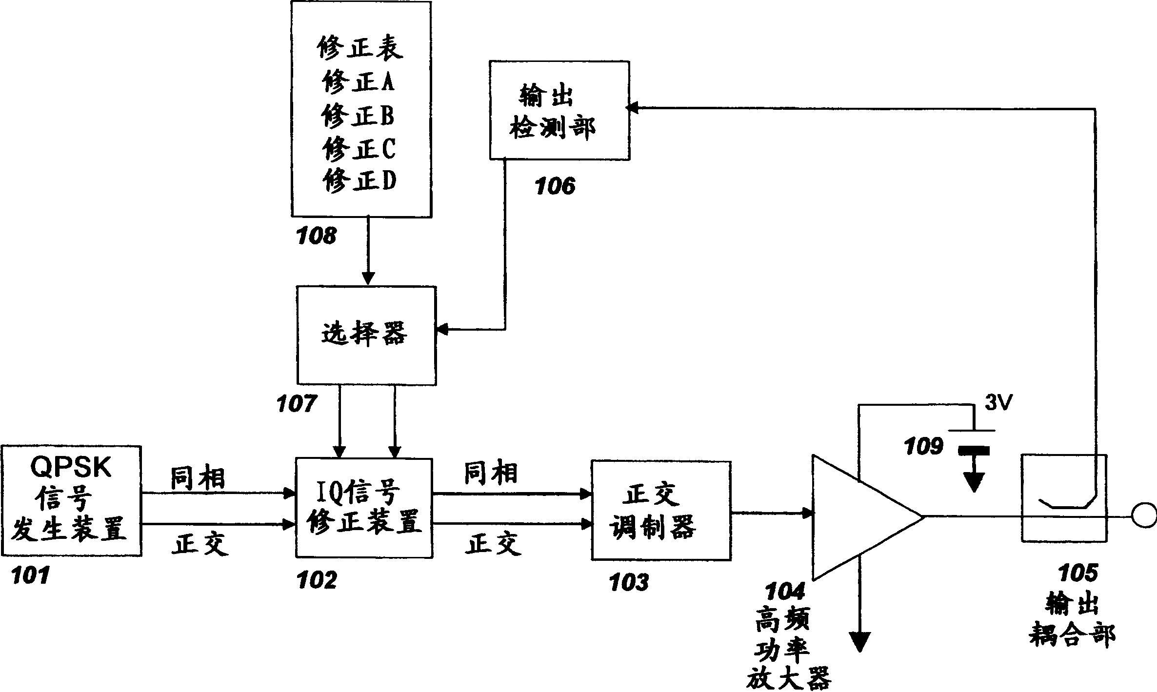
[0038] Embodiments of the present invention will be described below with reference to the drawings. In this embodiment, QPSK (Quadrature Phase Shift Keying: Quadrature Phase Shift Keying) is considered as the modulation wave. QPSK is a 4-value digital modulation method. By vector combining the in-phase signal (I) in the same direction as the X-axis and the quadrature signal (Q) in the same direction as the Y-axis with a phase difference of 90 degrees from the in-phase signal, the Digital signals are mapped on XY coordinates.

[0039] figure 1 is a block diagram showing the configuration of the transmitter according to the first embodiment of the present invention. The transmitter as figure 1 As shown, it consists of QPSK signal generator 101, IQ signal correction device 102, quadrature modulator 103, high frequency power amplifier 104, output coupling part 105, output detection part 106, selector 107, correction table 108 and power supply 109.

[0040] The above-mentione...

Embodiment 2

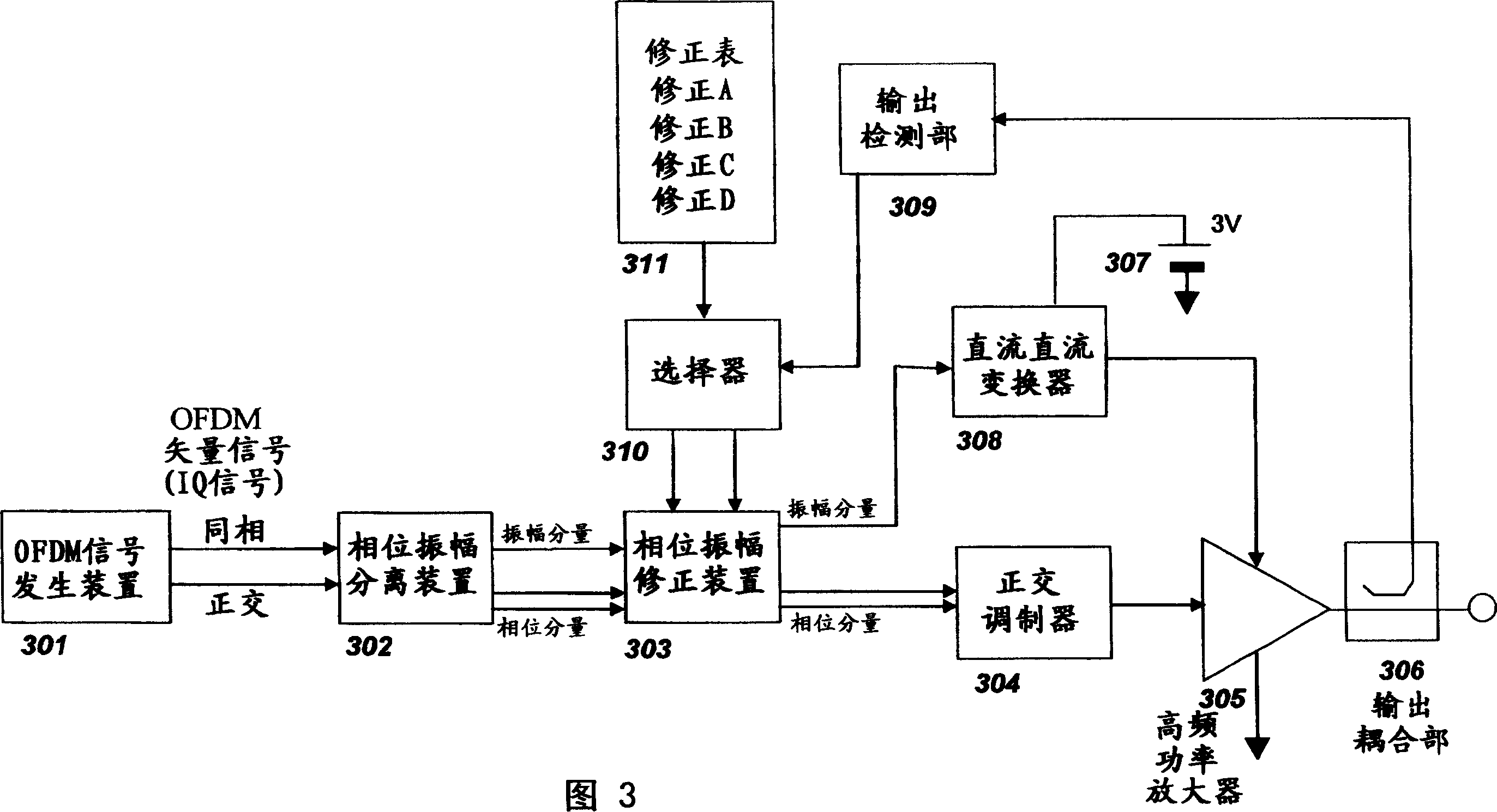
[0056] Next, Embodiment 2 of the present invention will be described with reference to the drawings. In this embodiment, an OFDM modulated wave signal is considered as the modulated wave signal. As a system using OFDM, for example, there is a wireless LAN system of the IEEE802.11a standard. In the wireless LAN system, for example, 64QAM modulation is performed on each of the 52 orthogonal subcarriers, and then multiplexed after inverse discrete Fourier transform to obtain an OFDM modulated wave signal. The 52 sub-carriers are respectively separated by 312.5kHz, and occupy 52*312.5=16.25MHz.

[0057] Fig. 3 is a block diagram showing a transmitter implementing the EER method according to an embodiment of the present invention. As shown in Figure 3, the transmitter consists of an OFDM signal generator 301, a phase-amplitude separation device 302, a phase-amplitude correction device 303, a quadrature modulator 304, a high-frequency power amplifier 305, an output coupling sectio...


PUM


Abstract

The amplitude component and phase component in the modulation signal are respectively input to the high frequency input terminal and the power supply terminal of the high frequency power amplifier, and the original modulated wave is obtained from the output of the high frequency power amplifier. Use the output detector to detect the output of the high-frequency power amplifier, use the selector to select the correction data for the detection voltage closest to the detection voltage from the correction data table measured and stored in various temperature environments in advance, and use the phase amplitude correction The device performs the correction of the amplitude component and the phase component. Therefore, it is possible to perform EER operation without causing spectrum degradation.

Description

technical field [0001] The present invention relates to wireless transmitters. Background technique [0002] Generally, in a modulated signal accompanied by amplitude modulation, especially in multilevel modulation such as QAM (Quadrature Amplitude Modulation), it is necessary to linearly operate a high-frequency power amplifier for transmitting power to an antenna. Therefore, as the operation type of the high-frequency power amplifier, class A or class AB is used. [0003] However, with the increase in bandwidth of communication, a communication method using multi-carriers such as OFDM (Orthogonal Frequency Division Multiplex: Orthogonal Frequency Division Multiplexing) has begun to be adopted. As a result, conventional class A and class AB high-frequency power amplifiers cannot achieve high efficiency. That is, in OFDM, by utilizing overlapping of subcarriers, high power is instantaneously generated completely randomly. Therefore, the ratio of the average power to the p...

Claims


Application Information

Patent Timeline
Patent Type & Authority Applications(China)
IPC IPC(8): H01Q11/12H03F1/30H03F1/32H03F3/24H04B1/04H04L27/20H04L27/36
CPCH03F1/3247H03F1/3294H04B2001/0433H03F1/34H03F3/24
Inventor 田边充田中宏一郎
Owner PANASONIC CORP
Why Eureka
Try Eureka