Chip having high sensitivity for silicon micro-capacitor microphone and preparation method thereof

A condenser microphone and high-sensitivity technology, applied in the direction of sensors, electrical components, etc., can solve the problems of microphone sensitivity drop, aging cracking, etc., and achieve the effects of avoiding aging cracking, reducing corrosion, and improving sensitivity

Inactive Publication Date: 2005-06-22
INST OF ACOUSTICS CHINESE ACAD OF SCI
View PDF0 Cites 4 Cited by
  • Summary
  • Abstract
  • Description
  • Claims
  • Application Information

AI Technical Summary

Problems solved by technology

[0003] The purpose of the present invention is to overcome the defects that the square vibrating membrane produced by the existing manufacturing process has a large stress at the sharp corner, which leads to a decrease in the sensitivity of the microphone and even an aging crack, thereby providing a circular isolation layer and a circular diaphragm. Chip for silicon microcapacitance microphone with high sensitivity and uniform circular microperforation on the edge of vibrating membrane and its preparation method

Method used


Image

  • Chip having high sensitivity for silicon micro-capacitor microphone and preparation method thereof
  • Chip having high sensitivity for silicon micro-capacitor microphone and preparation method thereof
  • Chip having high sensitivity for silicon micro-capacitor microphone and preparation method thereof

Examples


Embodiment 1

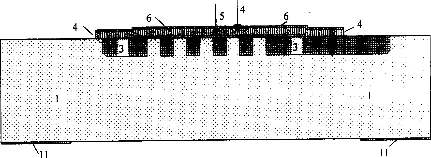
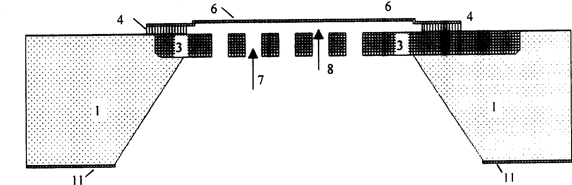
[0038] A kind of chip of the present invention that this embodiment provides is used in silicon microcapacitance microphone, see appendix Figure 4-6 ; The chip includes an n-type silicon substrate 1, and boron is diffused on the front side of the silicon substrate 1 to form a p+ type doped layer 3 with a thickness of 3 or 20 microns; at the p+ type doped layer 3, silicon dioxide is deposited and photoetched , Corroded into a ring-shaped isolation layer 4, the inner diameter of the annular isolation layer 4 is 500 or 3000 microns, and the radial width is 50 or 150 microns; a circular vibration made of silicon nitride is attached to the isolation layer 4 The film layer 6 is deposited on the vibrating film layer 6 and photoetched and corroded into a circular metal aluminum film and a square electrode 9, and uniform circular micro-perforations 10 are distributed on the edge of the vibrating film and the circular aluminum film; the circular The micro-perforation 10 has a diameter ...

Embodiment 2

[0040] combined with Figure 7 The preparation method of the present invention is described in detail with specific examples:

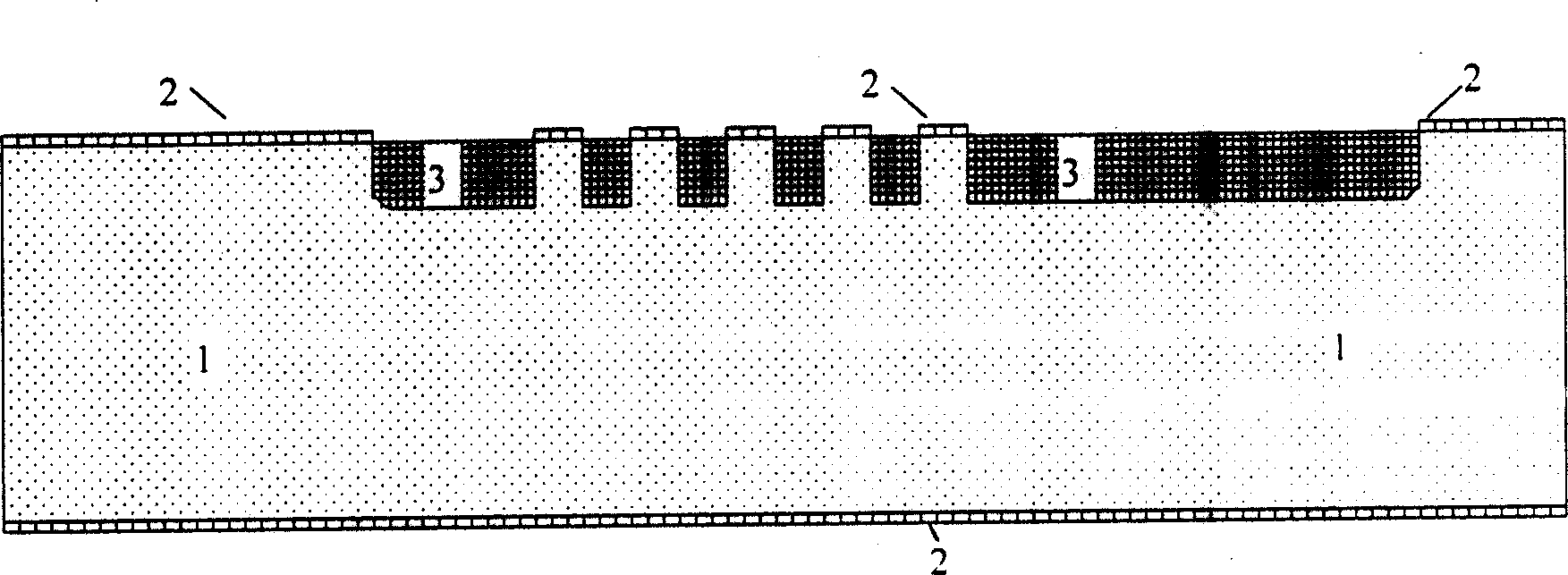
[0041] [1] Take an n-type silicon substrate 1 and grow a silicon dioxide with a thickness of 1.5 microns through high-temperature oxidation. After photolithography, use hydrofluoric acid to etch the high-temperature silicon dioxide to make a mask 2, and place it Carry out deep boron diffusion to form the p+ type doped layer 3 in the perforated backplane except for the hole distribution part, and the boron diffusion depth is 10 microns;

[0042] [2] After removing the high-temperature silicon dioxide mask with hydrofluoric acid, a 0.5-micron-thick zinc oxide auxiliary sacrificial layer is magnetron sputtered on the front of the silicon wafer, and a circular auxiliary sacrificial layer 5 is formed by photolithography and phosphoric acid etching. The diameter of the auxiliary sacrificial layer is 1000 microns, and the thickness is 0.5 microns; on the fr...


PUM

PropertyMeasurementUnit
thicknessaaaaaaaaaa
widthaaaaaaaaaa
diameteraaaaaaaaaa

Abstract

This invention refers to a chip used in silicon micro capacitance microphone and preparation method thereof, said chip contains a N negative type silicon substrate, P positive type doped layer formed by boron diffusion on positive surface of silicon substrate, silicon dioxide deposited on it, etching isolation layer adhered with a vibration membrane layer deposited with metal aluminium membrane layer then photo etching and corroding to form round aluminium membrane and rectangle aluminium electrode, a silicon nitride protective film on back surface of silicon substrate, corroding a trapeze notch with depth to P positive doped layer and corroding acoustics hole in vertical direction to form perforation back board which and silicon nitride vibration membrane form air gap. Said invention reduces vibration membrane stress and greatly raises the sensitivity of vibration membrane and avoids aging crack.

Description

technical field [0001] The invention relates to the field of silicon microcapacitor microphones, in particular to a high-sensitivity chip for silicon microcapacitor microphones and a preparation method thereof. Background technique [0002] The silicon microcapacitor microphone is composed of a silicon chip part and a peripheral circuit part forming a silicon microcapacitor, wherein the silicon chip part consists of a silicon substrate and a perforated (acoustic hole) backplane, air gap, isolation layer, vibrating membrane, and metal film. and metal electrodes. The usual silicon microcapacitor microphone is limited by the production method, and the air gap, isolation layer, and diaphragm are generally square, such as Micro Electro Mechanical Systems (MEMS), 1998 IEEE11th International Workshop p580-585, by P.-C. As described in "A HIGH SENSITIVITY POLYSILICON DIAPHRAGM CONDENSERMICROPHONE" by Hsu, C.H. Mastrangelo, and K.D. Wise. When making the silicon microcapacitor micr...

Claims


Application Information

Patent Timeline
Patent Type & Authority Applications(China)
IPC IPC(8): H04R9/08H04R31/00
Inventor 徐联汪承灏李晓东魏建辉黄歆
Owner INST OF ACOUSTICS CHINESE ACAD OF SCI
Why Eureka
Try Eureka