Method and apparatus for recycling hydrocarbon resource

A technology of treatment device and oxidant, applied in the details of gasification device, chemical instruments and methods, mechanical details of gasification device, etc., can solve the problem of poor gasification performance, difficulty in recycling waste, sensible heat loss and furnace heat loss major problems, to achieve the effect of cost reduction, energy consumption, and energy reduction

Inactive Publication Date: 2005-07-13
MITSUBISHI MATERIALS CORP
View PDF4 Cites 5 Cited by
  • Summary
  • Abstract
  • Description
  • Claims
  • Application Information

AI Technical Summary

Problems solved by technology

[0030] However, in the gasification method of the above-mentioned prior art, in order to improve the gas conversion efficiency, an extremely high temperature is required, and therefore, since the sensible heat loss of the generated gas and the furnace heat loss become large, there is a problem that the gasification performance is poor.
[0031] Moreover, accordin...

Method used


Image

  • Method and apparatus for recycling hydrocarbon resource
  • Method and apparatus for recycling hydrocarbon resource
  • Method and apparatus for recycling hydrocarbon resource

Examples


Embodiment 3

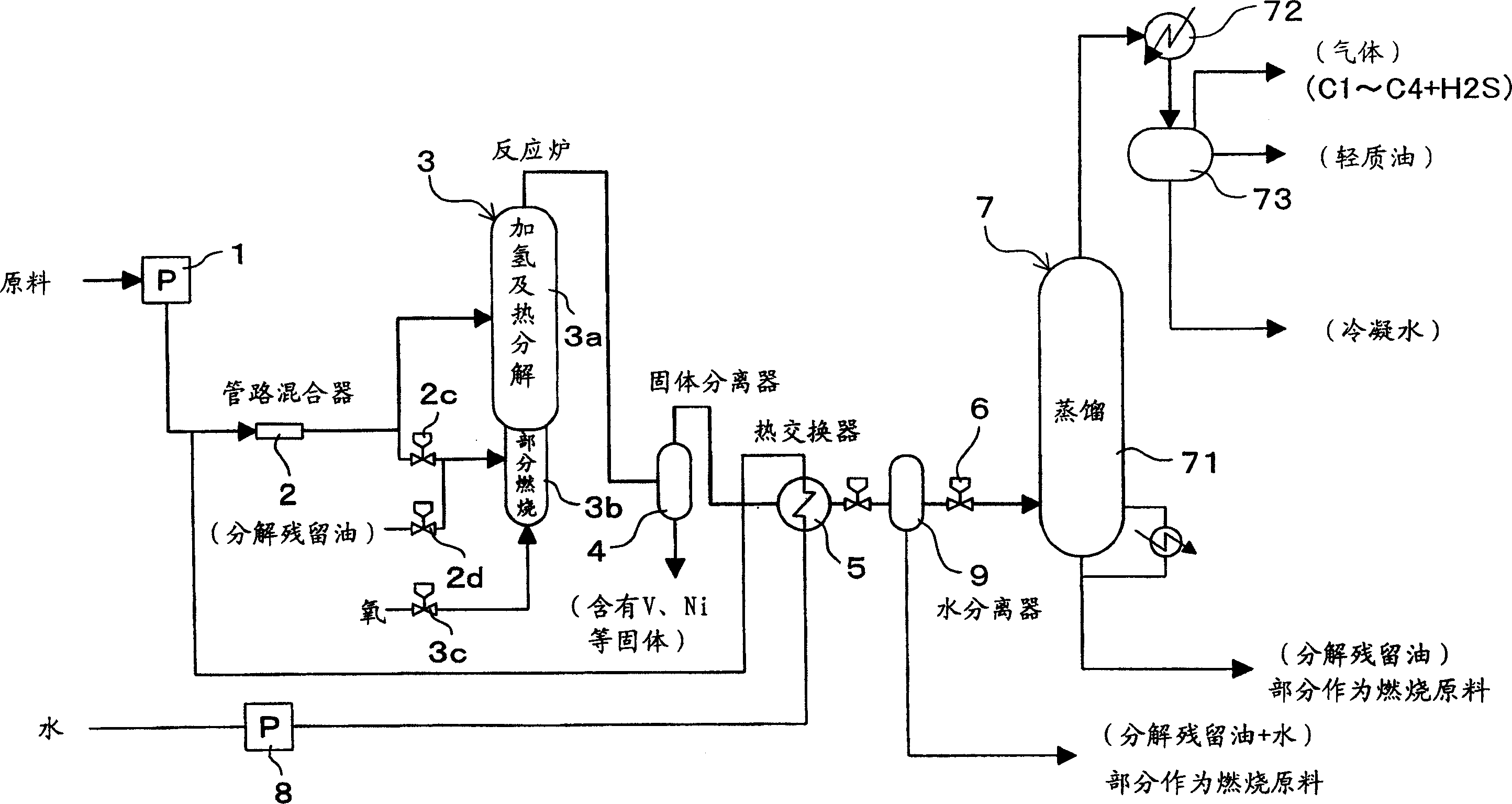
[0303] Example 3 is an experiment of thermally decomposing heavy oil without partial combustion, and under conditions of high temperature and high pressure water in the thermal decomposition zone 203 a of 550° C. and a pressure of 25 MPa in the reaction furnace 203 .

[0304] In addition, Comparative Example 2 is the reference data of other people's literature that adopts the Eureka (EUREKA) process of the existing thermal decomposition process to carry out thermal decomposition of heavy oil, and Comparative Example 3 is the HSC that adopts the existing thermal decomposition process ( Highway) process for thermal decomposition of heavy oils cited data from others.

[0305] In addition, in Table 2, V represents vanadium, and ND represents a value below the detection lower limit.

[0306] It can be confirmed from Table 2 that, compared with Comparative Examples 2 and 3, Example 3 of the present invention is superior in light oil yield, sulfur removal ability, impurity removal ab...

Embodiment 4

[0315] The conditions of Example 4 were 560° C. in the partial combustion region 203 b , 510° C. in the thermal decomposition region 203 a other than the partial combustion region 203 b , and 25 MPa in the reaction vessel 232 .

Embodiment 5

[0316] The conditions of Example 5 were 640° C. in the partial combustion region 203 b , 590° C. in the thermal decomposition region 203 a other than the partial combustion region 203 b , and 25 MPa in the reaction vessel 232 .


PUM


Abstract

The present invention provides a method and an apparatus for effectively performing thermal decomposition without using a catalyst and without supplying hydrogen from the outside, and improving the yield of oil components and pyrolysis gas. In the present invention, the raw material can be fully utilized by gasifying the residue components generated by thermal decomposition to form combustible gas. Furthermore, the present invention provides a method for separately separating metal impurities contained in a raw material as a solid, and is a novel method and apparatus capable of improving availability as resources. In a preferred form of the present invention, nozzles (raw material supply mechanism, oxidant supply mechanism, water supply mechanism) (103) are provided in the reaction vessel (102), and a heat exchanger (104) is provided to A high-temperature and high-pressure generated gas is introduced between the pressure vessel (101) and the reaction vessel (102), and the high-temperature and high-pressure generated gas is generated by reacting oxygen in the raw material and the oxidant in the reaction vessel (102) under water atmosphere conditions. , the pressure vessel (101) is provided with a water inlet (114) communicated with the water supply pipeline (106), and is provided with a discharge pipeline (105) for inserting the generated gas communicated with the heat exchanger (104). ), and a flow path for supplying water between the pressure vessel (101) and the reaction vessel (102) into the reaction vessel (102) is provided in the nozzle (103).

Description

technical field [0001] The present invention relates to a technique for upgrading heavy substances produced in petroleum refining or coal-to-oil conversion industries such as atmospheric distillation residues and vacuum distillation residues, or for upgrading natural heavy oils, etc. Quality, and the conversion of petroleum products such as waste plastics into their original raw materials, thereby increasing the cycle rate and improving economic efficiency in each production site. [0002] The present invention also relates to a reaction treatment device under high-temperature and high-pressure water atmosphere conditions, which is used to regenerate fossil fuels such as coal, petroleum, and natural tar, organic waste such as waste plastics, and sewage sludge, and biomass. Recycled resources, etc. are reacted under high temperature and high pressure water atmosphere conditions to recover energy from these resources or upgrade them into light fuels. [0003] The present invent...

Claims


Application Information

Patent Timeline
IPC IPC(8): C10G9/38C10J3/58C10J3/66C10J3/78
CPCC01B3/34C01B3/48C01B2203/0216C01B2203/0222C01B2203/0255C01B2203/0283C01B2203/06C01B2203/063C01B2203/0811C01B2203/0894C01B2203/1252C01B2203/1276C01B2203/1294C01B2203/142C01B2203/1628C01B2203/82C10G9/38C10J3/466C10J3/58C10J3/66C10J3/78C10J2200/09C10J2200/15C10J2200/152C10J2300/0979C10J2300/1696C10J2300/1892C10K3/006C10K3/008C10K3/04Y02P20/52
Inventor 田中皓太田和明戴文斌斋木涉白刚森良平
Owner MITSUBISHI MATERIALS CORP
Why Eureka
Try Eureka