Controlling media particle size in slurried dense media separations

A particle size and density separation technology, applied in wet separation, solid separation, electrostatic effect separation, etc., to improve separation performance and reduce foam

Inactive Publication Date: 2005-10-26
MBA POLYMERS INC
View PDF1 Cites 8 Cited by
  • Summary
  • Abstract
  • Description
  • Claims
  • Application Information

AI Technical Summary

Problems solved by technology

However, there is no system today that is broadly applicable to polymer

Method used


Image

  • Controlling media particle size in slurried dense media separations
  • Controlling media particle size in slurried dense media separations
  • Controlling media particle size in slurried dense media separations

Examples


example 1

[0077] Example 1: Effect of Media Particle Size on Plastic Surface Contamination

[0078] Magnetite with a particle size distribution in the range of 0.1 to 100 microns was placed in water and stirred. The slurry can settle for a few minutes and make-up fluid injected into the second container. This slurry is allowed to settle for a few minutes and then make-up fluid is injected into a third container. Each container holds a portion of coarse, intermediate, or fine medium size.

[0079] About 10 grams of polypropylene pellets were stirred in each of the three slurries for about 1 minute. The pellets are then removed, rinsed and oven dried. The pellets stirred with the fine particle slurry appeared significantly darker than the pellets stirred with the coarse or intermediate magnetite slurries.

[0080] The charge of the dried pellets was then measured after spinning in a polycarbonate container. Table 2 shows the charge per mass unit on spheroids of fine and coarse partic...

example 2

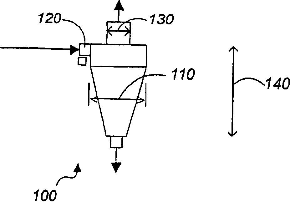
[0083] A 15-inch Model D15B hydrocyclone manufactured by Krebs Engineers, Tucson, Arizona, with a 6-inch vortex finder, an 11-square-inch inlet, and a 4.5-inch top supplies magnetite at about 7 psi and removes Particles above about 30 microns. Alternatively, by repeating the process or decreasing the separation cut point by increasing the feed rate, or changing another cyclone separation parameter, additional particles up to about 25 microns can be removed, yielding media of very close size 5-25 microns, as shown in Table 1 Show. The hydrocyclones were positioned at approximately 22 degrees from horizontal. The hydrocyclone distributes roughly half of the ~30 micron particles to the underflow, with a higher percentage of coarser particles to the underflow. About 30-40% of the total fluid is sent to the underflow, which will not effectively classify only 30-40% of the particles recovered to the underflow because it comes with the fluid and is not swirled. Streamer function. ...

example 3

[0085]Another example of selecting a media size is as follows. A model D4B-12 hydrocyclone manufactured by Krebs Engineers, with a 1.2 square inch inlet area, a 1.25 inch vortex finder, and a feed pressure of about 30 psi, expects about half of the 10 micron particle magnetite The slurry is recycled to the underflow. With a top diameter of 0.625, this cyclone sends about 10% of the total fluid to the underflow. As such, it concentrates particles coarser than 10 microns and may have very little ability to capture particles of 5 microns or smaller in the underflow. About 10% of all smaller particles are diverted to the underflow as they travel with the fluid reaching the underflow. In each pass, between 50 and 90% of all particles below 10 microns are removed from the media reaching the underflow. After passing through the cyclone 1-5 times, the magnetite recovered to the underflow will basically have no particles of 5 microns and below.


PUM

PropertyMeasurementUnit
Particle sizeaaaaaaaaaa

Abstract

Methods, systems, and media for use in separating mixtures. A slurry including a separation liquid and one or more particulate media materials is provided. A classification separation is performed on the slurry to produce a classified media having a controlled particle size distribution of the particulate media materials. The classified media is combined with a mixture to be separated to generate a separation mixture. A density separation is performed on the separation mixture. The particle size distribution can be controlled based in part on characteristics of components of a separation system to be used in subsequent density separations.

Description

[0001] Cross References to Related Applications [0002] This application claims the benefit of Provisional Application No. 60 / 397808, filed July 22, 2002, the contents of which are hereby incorporated by reference. field of invention [0003] The present invention relates to material separation and recycling of plastics. Background technique [0004] The problem of separating different polymeric materials from each other is a major obstacle to the economical recovery of polymeric materials from durable goods. There are currently three main separation techniques: manual sorting, optical / beam-splitting based sorting, and mechanical sorting mainly based on material density differences. Manual sorting is labor intensive and in most cases prohibitive due to cost. Optical-based sorting techniques, including visible light, near-infrared, ultraviolet light, and X-ray fluorescence, have many applications, and these systems will undoubtedly play a role in future recycling devices, ...

Claims


Application Information

Patent Timeline
IPC IPC(8): B03B5/30B03B5/32B03B5/34B03C7/00B29B17/02B29C48/03B29C48/29
CPCB29B2017/0203B29B2017/0224B29K2069/00B29K2105/065B03C7/00B29L2030/00B29K2105/0005B29K2105/0044B03B5/34B29C47/1045B29K2105/0032B29K2105/16B29K2023/12B29K2021/00B29C47/0004B29B17/02B29B2017/0265B29B2017/0241B29B2017/0262B29K2077/00B29B2017/0279B29C47/0009B29B2017/0244B29C47/1063B29K2027/06B03B5/447B29K2055/02B29B2017/0237B29C48/29B29C48/022B29C48/03B29C48/2886Y02W30/52Y02W30/62
Inventor L·E·艾伦三世
Owner MBA POLYMERS INC
Why Eureka
Try Eureka