
MZ interference evanescent wave chemical and biological sensor and system with fibre-optical microstructure

A biosensor and microstructure technology, applied in the fields of biology, chemistry, and optical fiber sensing, can solve the problems of affecting measurement accuracy, difficulty in alignment and debugging, and large size, and achieve high measurement accuracy and sensitivity, good controllability of production quality, The effect of structural miniaturization

Inactive Publication Date: 2005-12-28
重庆工学院
View PDF0 Cites 5 Cited by
  • Summary
  • Abstract
  • Description
  • Claims
  • Application Information

AI Technical Summary

Problems solved by technology

[0008] At present, the optical fiber evanescent wave biosensor still has some disadvantages: (1) The fabrication of the sensor is cumbersome and difficult, and the optical fiber cladding needs to be removed by chemical corrosion or abrasion, and the removal position of the optical fiber cladding is difficult to precisely control
At the same time, the surface of the fiber core after chemical corrosion or abrasion of the fiber cladding is a rough non-optical interface, which affects the optical performance at the interface, and the noise of the signal light is very large, which affects the measurement accuracy
(2) The sensing system uses a single optical path intensity measurement method. The fluctuation and interference of the light source, optical path and circuit system have a great impact on the reliability and accuracy of the sensing system, and it is difficult to achieve higher precision biomolecular measurement and measurement. analyze
(3) The influence of stray light interference is great, and stray light outside the fiber core can also excite fluorescence, thereby affecting the detection results, so it is necessary to shield stray light
(4) The data has no fault tolerance, and the sensing system has no telemetry capability
The optical fiber used in the method and its system is a section of multimode optical fiber with a length of about 40cm and an outer diameter of 1mm. This section of optical fiber is only used as a sensing head, and it is not used as a transmission medium, and the advantages of the optical fiber are not fully utilized.
(5) The system structure is complex: the sensing system does not use modern optical miniaturization and fiber optic technology, but uses conventional optical components to form the system. The system structure is complex and huge, and alignment and debugging are very difficult. Interference has a big impact
The structure of the photoelectric detection and processing system to meet this requirement is complex and large

Method used


Image

  • MZ interference evanescent wave chemical and biological sensor and system with fibre-optical microstructure
  • MZ interference evanescent wave chemical and biological sensor and system with fibre-optical microstructure
  • MZ interference evanescent wave chemical and biological sensor and system with fibre-optical microstructure

Examples


Embodiment Construction

[0021] Taking the measurement of human IgG as an example, the implementation of the above-mentioned sensor and sensing system will be further described in conjunction with the accompanying drawings. The implementation of measuring other chemical components or biomolecules in the form of gas or solution is similar to it, the difference is only in the optical fiber cladding Curing a layer of different biomolecular or chemical composition sensitive film layer only.

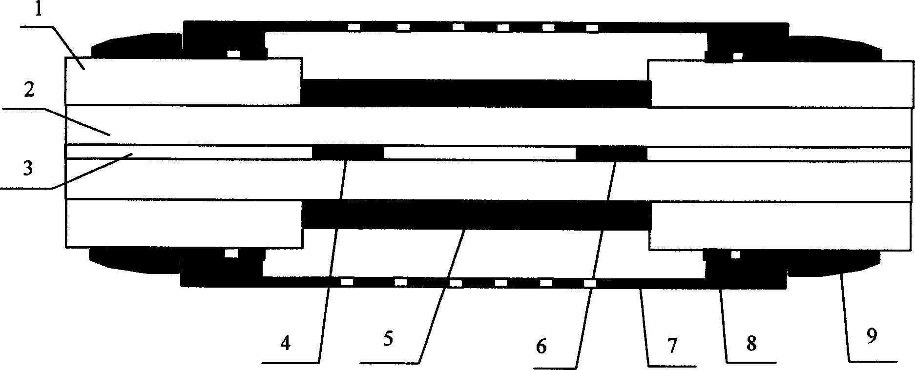
[0022] see figure 1 , the structure of the sensor includes: optical fiber coating layer 1, optical fiber cladding layer 2, optical fiber core 3, long period fiber grating LPFG1 4, biomolecule human IgG sensitive film layer 5, long period fiber grating LPFG2 6, protective cover 7, Curing glue 8, transition buffer sleeve 9. The manufacturing method is as follows: (1) Remove a section of plastic protective coating of an ordinary optical fiber (the optical fiber material is quartz or plastic, the core diameter is about ...


PUM

PropertyMeasurementUnit
Thicknessaaaaaaaaaa
Lengthaaaaaaaaaa

Abstract

A chemical and biological transducer is prepared by setting two long period fibre gratings, fibre core and fibre covering on one piece of fibre to form a MZ interferometer and then placing a film layer sensitive to chemical or biological molecule on fibre covering surface to form evanescent wave transducer of fibre MZ interferometer structure. The sensing system comprises light source of wide band, optical fibre, chemical and biological transducer of evanescent wave and MZ interference in optical microstructure, fibre spectrograph and computer.

Description

technical field [0001] The invention belongs to the technical fields of optical fiber sensing, biology and chemistry, and in particular relates to an optical fiber microstructure MZ interference type evanescent wave chemical and biological sensor and system. Background technique [0002] Optical fiber chemical and biological sensors are a new type of sensing technology that was born in the mid-1970s. This sensor is an indicator dye, enzyme, coenzyme, biological receptor, antigen, Antibodies, nucleic acids, DNA, animal and plant tissues or cells, microorganisms, polymer materials, etc., sensitive membranes, sol-gels or themselves, adsorbed, solidified or installed on optical fibers, planar optical waveguides, capillary waveguides, and the to-be-treated samples in the sample Selective chemical or biomolecular recognition of the detected substance, and then converted into various optical information, so as to obtain chemical and biological information. In most sensors, the opt...

Claims


Application Information

Patent Timeline
IPC IPC(8): G01N21/17
Inventor 曾祥楷
Owner 重庆工学院
Learn More