Cleaning and servicing technology for turbine blade basal body surface by strong current pulsed ionizing beam

A high-current pulse, turbine blade technology, used in blade support elements, engine elements, machines/engines, etc., can solve problems such as coating fracture failure, environmental pollution, and blade coating performance degradation, and achieve smooth and smooth processing surfaces. Effect

Active Publication Date: 2006-02-22
DALIAN UNIV OF TECH
View PDF1 Cites 6 Cited by
  • Summary
  • Abstract
  • Description
  • Claims
  • Application Information

AI Technical Summary

Problems solved by technology

[0002] There are only a handful of countries in the world that can independently develop aero-engines, far less than those that can independently develop advanced aircraft. The life of turbine blades is the limiting factor that determines the performance of modern high-performance jet engines. Although these components are carefully selected during design Excellent superalloy and special cooling structure, but in the engine service process, the turbine blade is one of the weak links; with the development of the engine combustion chamber in the direction of high flow ratio, high thrust-to-weight ratio and high inlet temperature, the combustion chamber in the combustion chamber The combustion temperature and pressure are constantly increasing. In order to adapt to this harsh working environment, double-layer, multi-layer and gradient thermal barrier coatings have been developed. At present, double-layer thermal barrier coatings have been put into use; however, the coating on the surface of the alloy is made of The double-layer thermal barrier coating composed of ceramic thermal insulation top layer and metal bonded bottom layer is easy to oxidize during long-term use. Oxide is formed between the substrates, and a large thermal stress is generated in the oxide, which leads to the failure of the coating along the interior of the oxide, the interface between the oxide and the metal bonding bottom layer, or the interface between the oxide and the ceramic thermal insulation top layer, so It is necessary to use a more economical and effective method to remove and recoat the failed double-layer thermal barrier coating, otherwise the high-cost blades will be scrapped due to the degradation of the coating performance, resulting in large losses; blade repair technology has become an aviation The key problems of the engine that need to be solved urgently
[0003] At present, the typical blade repair technology used is brazing repair, and the repair process is mainly: using spray stripping technology to remove the invalid ceramic insulation top layer on the blade, and the oxide between the ceramic heat insulation top layer a

Method used


Image

  • Cleaning and servicing technology for turbine blade basal body surface by strong current pulsed ionizing beam
  • Cleaning and servicing technology for turbine blade basal body surface by strong current pulsed ionizing beam
  • Cleaning and servicing technology for turbine blade basal body surface by strong current pulsed ionizing beam

Examples


Embodiment 1

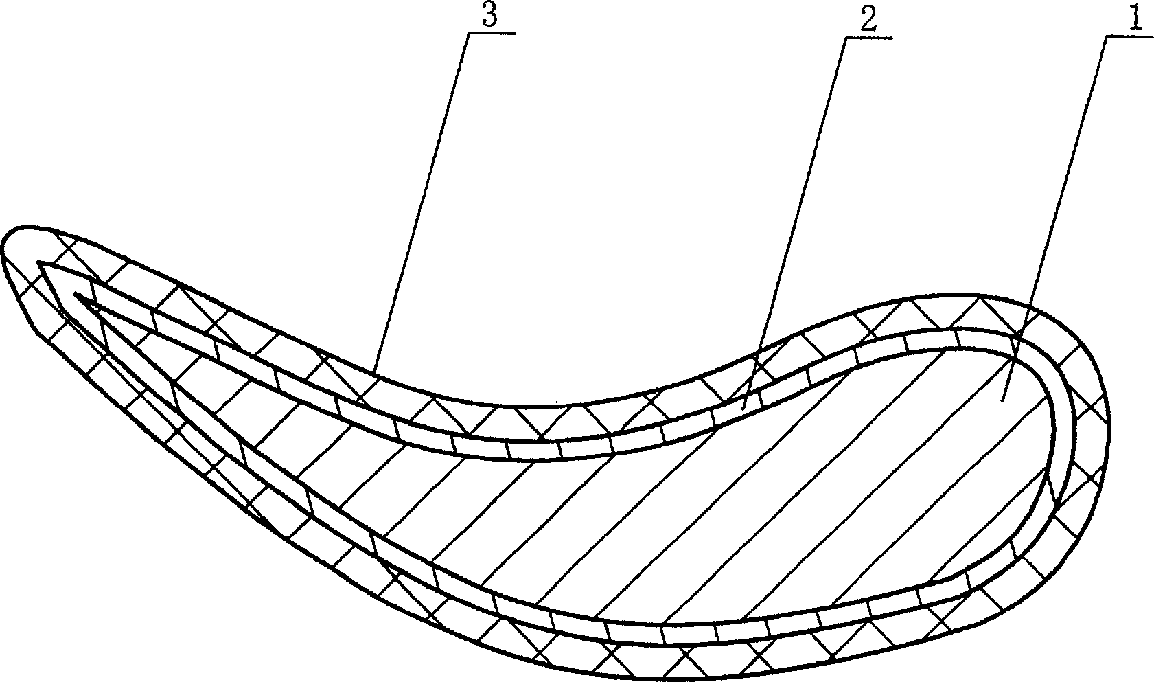
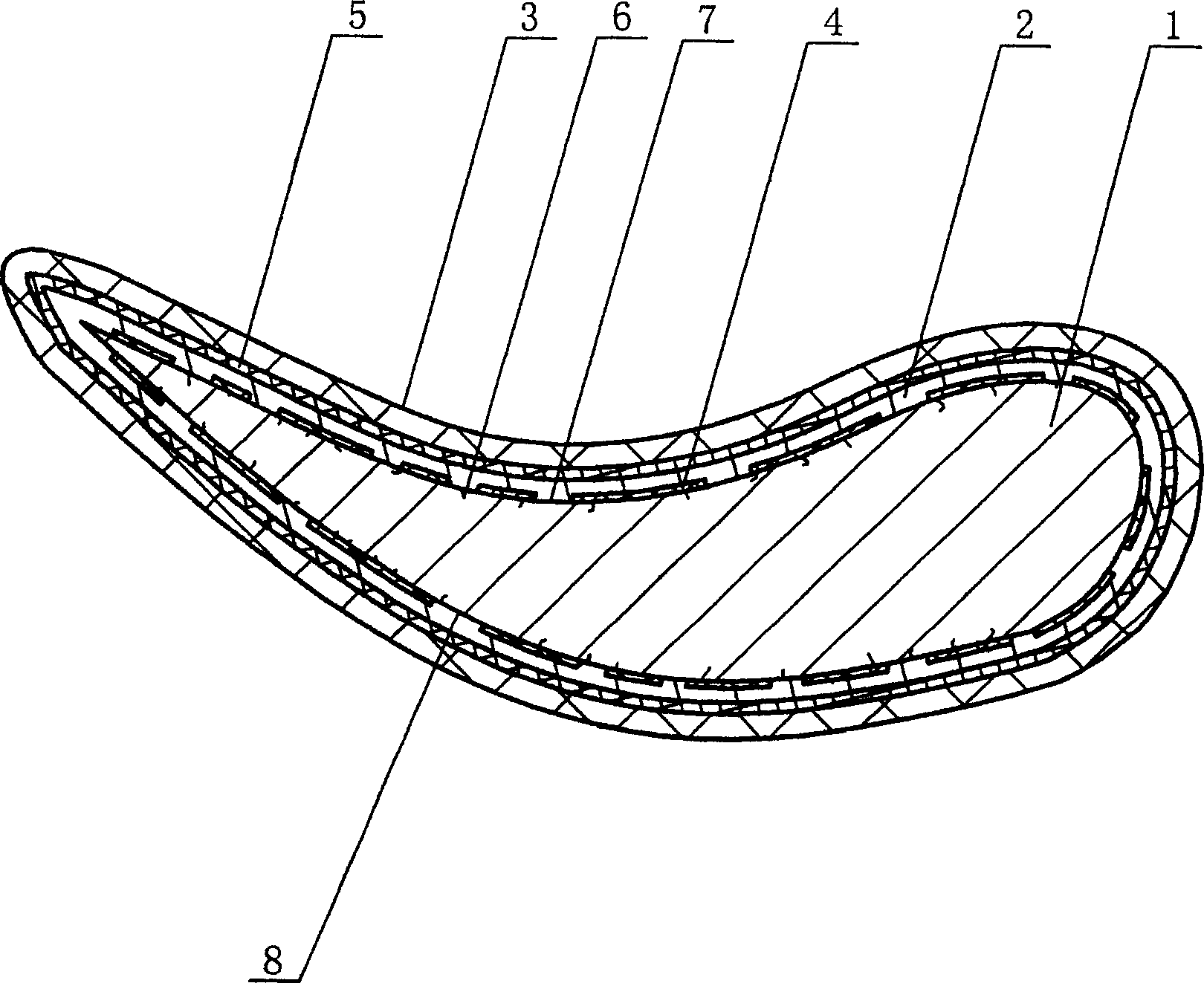
[0027] A company requires to clean the 0.1μm thick oxide [4] formed on the surface of the turbine blade matrix [1] that has been in service, and the removal thickness accuracy is required to reach ±0.02μm, and the blade processing surface is required to be smooth and the matrix does not produce deformation. The cleaning and maintenance technology for the surface of the turbine blade substrate with a high-current pulsed ion beam of the present invention has the following cleaning and maintenance process steps:

[0028] In the first step, place the blade with the ceramic heat-insulating top layer [3] and the metal bonded bottom layer [2] removed, and the oxide [5] formed therebetween, on the sample stage of the high-current pulsed ion beam device,

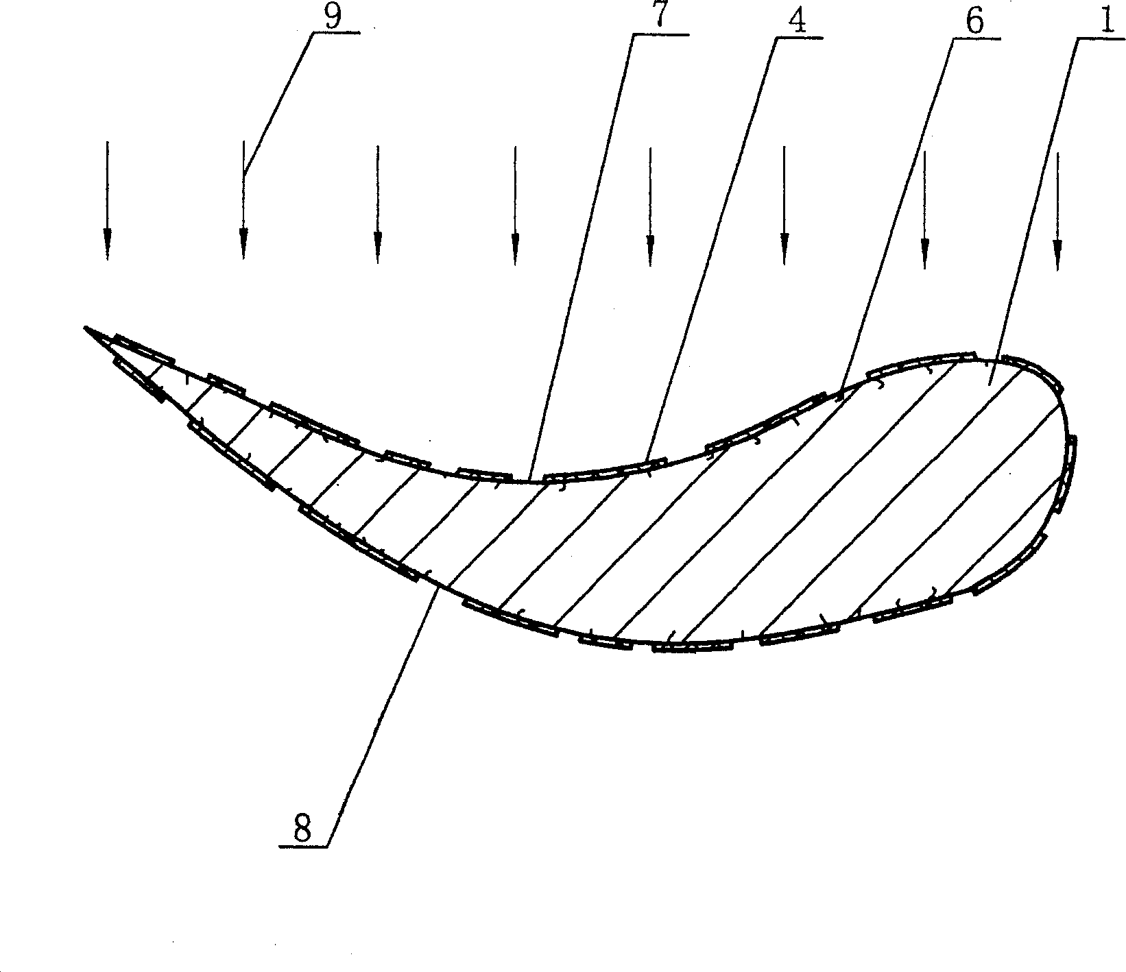
[0029] The blade is placed on the sample stage so that the front curved surface [7] of the blade is completely exposed to the beamline radiation area of ​​the high-current pulsed ion beam [9], the vacuum chamber of the device is close...

Embodiment 2

[0039] An aero-engine company required to clean the 8.2 μm thick oxide [4] formed on the surface of the turbine blade matrix [1] that had been in service, and the removal thickness accuracy was required to reach ±0.1 μm, and the blade processing surface was required to be smooth and flat without deformation of the matrix. Now adopt the cleaning and maintenance technology of the present invention with the high-current pulsed ion beam to the surface of the turbine blade substrate, and its cleaning and maintenance process steps are as follows:

[0040] In the first step, place the blade with the ceramic heat-insulating top layer [3] and the metal bonded bottom layer [2] removed, and the oxide [5] formed therebetween, on the sample stage of the high-current pulsed ion beam device,

[0041] The blade is placed on the sample stage so that the front curved surface [7] of the blade is completely exposed to the beamline radiation area of ​​the high-current pulsed ion beam [9], the vacuu...

Embodiment 3

[0051] A company requires to clean the 10μm thick oxide [4] formed on the surface of the turbine blade matrix [1] that has been in service. The removal thickness accuracy is required to reach ±0.1μm, and the blade processing surface is required to be smooth and flat without deformation of the matrix. Now this The cleaning and maintenance technology for the surface of the turbine blade substrate with the high-current pulsed ion beam invented, the cleaning and maintenance process steps are as follows:

[0052] In the first step, place the blade with the ceramic heat-insulating top layer [3] and the metal bonded bottom layer [2] removed, and the oxide [5] formed therebetween, on the sample stage of the high-current pulsed ion beam device,

[0053] The blade is placed on the sample stage so that the front curved surface [7] of the blade is completely exposed to the beamline radiation area of ​​the high-current pulsed ion beam [9], the vacuum chamber of the device is closed and vacu...


PUM

PropertyMeasurementUnit
Energy densityaaaaaaaaaa

Abstract

The invention relates to a turbine blades cleaning and mending technology in maintenance engineering, which comprises the following steps: first, placing turbine blades on sample table and exposing it in strong pulsed ionizing beam; second, radiating the blades for 1-20 times with strong pulsed ionizing beam of 5-60J/cm2 to remove oxide compound; third, radiating the blades for 1-10 times with strong pulsed ionizing beam of 1-5J/cm2 to weld microcrack; forth, rotating blades and cleaning back curved face. Compared with existing technology, the invention doesn't require high-temperature and corrosion-proof equipment and produces product with smooth surface.

Description

technical field [0001] The invention relates to a technology for cleaning and maintaining the surface of a turbine blade substrate by using a high-intensity pulsed ion beam (HIPIB), and belongs to the field of equipment maintenance engineering. Background technique [0002] There are only a handful of countries in the world that can independently develop aero-engines, far less than those that can independently develop advanced aircraft. The life of turbine blades is the limiting factor that determines the performance of modern high-performance jet engines. Although these components are carefully selected during design Excellent superalloy and special cooling structure, but in the engine service process, the turbine blade is one of the weak links; with the development of the engine combustion chamber in the direction of high flow ratio, high thrust-to-weight ratio and high inlet temperature, the combustion chamber in the combustion chamber The combustion temperature and press...

Claims


Application Information

Patent Timeline
IPC IPC(8): C23F17/00C23F1/04F01D5/28
Inventor 雷明凯苗收谋徐忠成韩晓光张智
Owner DALIAN UNIV OF TECH
Why Eureka
Try Eureka