Method of fabricating polyurethane foam with micro pores and polishing pad therefrom

A technology of polyurethane foam and polishing pad, applied in the field of polishing pad, can solve the problems of high production cost, damaged processing allowance, performance change, etc., and achieve the effects of reducing processing cost, increasing processing allowance, and increasing selection possibility

Inactive Publication Date: 2006-02-22
SK恩普士有限公司
View PDF3 Cites 9 Cited by
  • Summary
  • Abstract
  • Description
  • Claims
  • Application Information

AI Technical Summary

Problems solved by technology

That is, the processing margin of the preparation process is reduced due to poor retention performance and short maintenance life for keeping each component in the mixture
[0013] There is also the problem that mixing a creamy foam dispersion liquid with another first component liquid makes it difficult to mix the mixture effectively and easily, resulting in harsh preparation conditions and an increase in the overall time of the preparation process
Therefore, in order to prevent changes in the properties of the isocyanate-terminated urethane prepolymer, polysiloxane-based nonionic surfactants that do not contain hydroxyl groups should be selectively used, which results in greatly limiting the ability to satisfy various properties. Selection of required polishing pad composition
Moreover, polysiloxane-based nonionic surfactants containing hydroxyl groups are more widely used and are less costly, so the above-mentioned restrictions on the choice of this surfactant lead to higher production costs, and its processing margin also damaged

Method used


Image

  • Method of fabricating polyurethane foam with micro pores and polishing pad therefrom
  • Method of fabricating polyurethane foam with micro pores and polishing pad therefrom
  • Method of fabricating polyurethane foam with micro pores and polishing pad therefrom

Examples


Embodiment approach 1

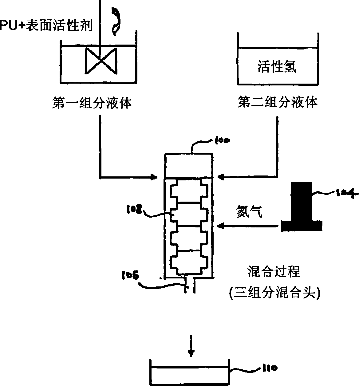
[0075] Such as figure 2 As shown in the schematic diagram of , 1 part by weight of a hydroxyl-containing silicone-based surfactant (trade name: DC-193, DOW CORNING Co., Ltd.) and 100 parts by weight of an isocyanate-terminated urethane prepolymer Adiprene L-325 were mixed and then reacted with each other at a temperature of 60°C for 2 hours. As a result, the hydroxyl group of the polysiloxane-based surfactant is deactivated and a uniform and stable urethane prepolymer reaction liquid (first component liquid) is obtained. This first component liquid is transferred to an air nucleation type molding machine 100, and then, a non-reactive gas N is injected thereinto using a mass flow meter 104. 2 , while injecting 24 parts by weight of MBCA (relative to 100 parts by weight of isocyanate-terminated urethane prepolymer Adiprene L-325) dissolved at a temperature of 120° C. as a second component liquid therein. Next, the mixture is mixed and stirred by the rotating paddle 108, and p...

Embodiment approach 2-9

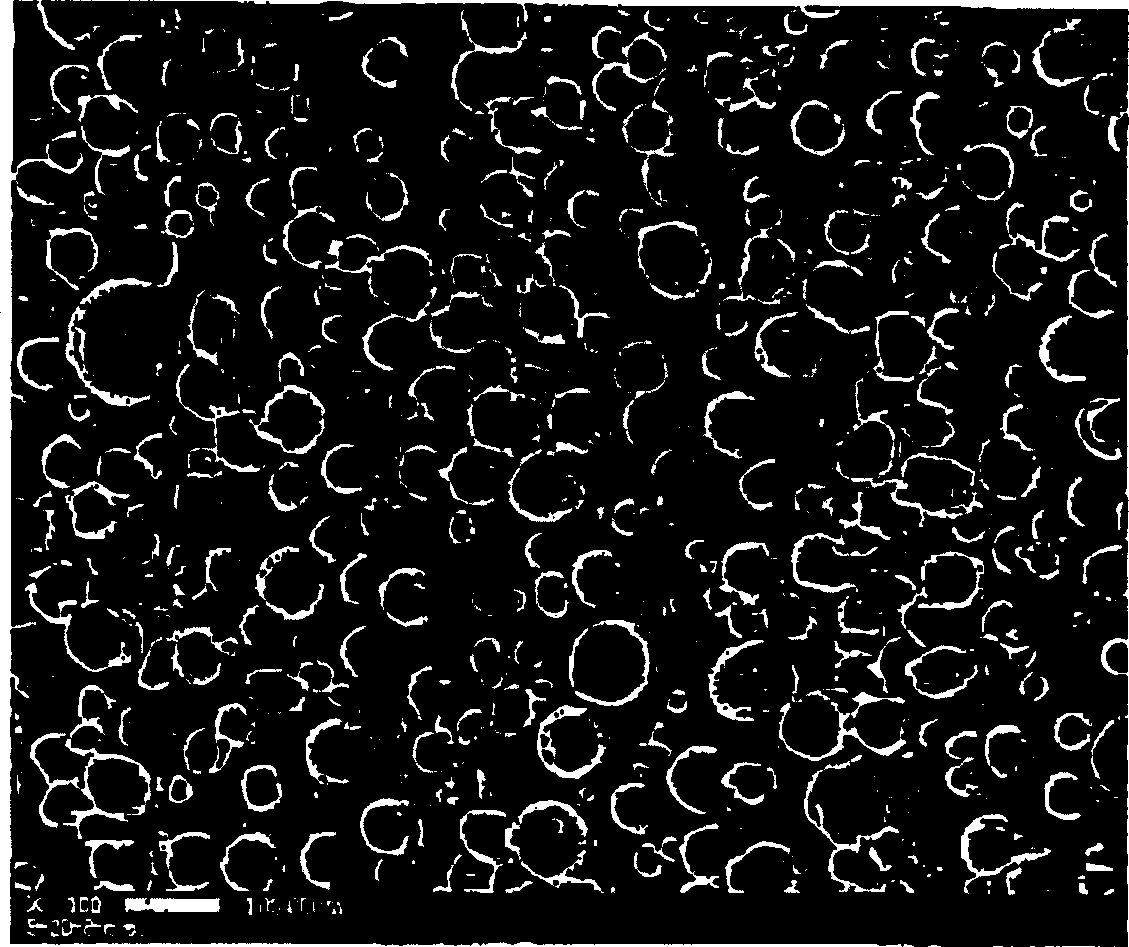
[0079] By the same method as Comparative Example 1, by changing the content of surfactant, the amount of poured mixture and the injection amount of non-reactive gas, etc., wherein the composition ratio is shown in Table 1 below, polishing pads were prepared, and these polishing pads were evaluated. The polishing properties of the pad. The evaluation results are shown in Table 2. The polishing pad prepared by Embodiment 2 was inspected by SEM, and it was found that the pores formed thereon were very uniform and fine. (see Figure 4 )

[0080] carbamic acid

Ethyl prepolymerized

matter (parts by weight)

hollow ball

(parts by weight)

Surfactant

(parts by weight)

active hydrogenation

compound (weight

share)

Mass Flow

meter control water

flat;

responsive injection

Quantity >; (L /

minute)

mix

the solution

row of

put

(kg...


PUM

PropertyMeasurementUnit
densityaaaaaaaaaa
sizeaaaaaaaaaa
sizeaaaaaaaaaa

Abstract

To provide a method of fabricating a polyurethane foam with micro pores, and a polishing pad therefrom, the method including steps of (a) adding a nonionic surfactant into at least one of a first ingredient including an isocyanate group-containing compound and a second ingredient including an active hydrogen group-containing compound, (b) agitating and mixing the mixture of the first ingredient and the second ingredient while adding a non-reactive gas thereto, (c) discharging the mixture out of a container at a predetermined rate, and (d) injecting the discharged mixture into a mold so as to form a mold body into a predetermined shape.

Description

technical field [0001] The present invention relates to a method of preparing a polyurethane foam having micropores and a polishing pad obtained therefrom, and more particularly to a method of preparing a polishing pad for planarization of semiconductor wafers by chemical mechanical polishing (CMP) and to a polishing pad obtained therefrom polishing pad. Background technique [0002] In recent years, with the high integration of semiconductor elements, the fineness and compactness of the line patterns on them have also increased rapidly. In this regard, an exposure process for transferring a pattern on a semiconductor wafer is an important process, but improvements in the exposure process alone are not enough to satisfy the recent above-mentioned requirements. Also, the number of layers formed on the wafer increases with the rapid development of the trend towards high integration, and the roughness of the wafer surface increases, so that it may be diff...

Claims


Application Information

Patent Timeline
Patent Type & Authority Applications(China)
IPC IPC(8): C08G18/10C08G18/63H01L21/304B24B37/00B24B37/20B24D13/14C08G18/00C08G18/08C08G18/12C08G18/82C08G101/00C08J9/12C08J9/30C08K5/54C08K7/22C08L75/04
CPCC08K5/54C08J2375/04B24B37/24C08G18/12C08G2101/00C08J9/30C08G18/61C08G18/3808C08L75/04C08G18/10C08G18/82C08J9/12
Inventor 李圭敦车允钟
Owner SK恩普士有限公司
Why Eureka
Try Eureka